Table of Contents
Advertisement
Quick Links
Uninterruptible power supply of 8 IP cameras (52V DC)
Uninterruptible power supply of the recorder (12V DC)
Switch 10 ports
8 PoE ports 10/100 Mb/s, (data and power supply)
2 ports 10/100 Mb/s (UpLink)
30W for each PoE port, supports devices complaint with
the IEEE802.3af/at (PoE+) standard
Approximate backup time: 3h 15min
CONTENTS
S108-BR 10-ports switch with buffer power supply
for 8 IP cameras and recorder
Edition: 2 from 16.04.2018
Supercedes the edition: 1 from 01.03.2017
Features
:
Example of use .
1
S108-BR
v1.0
LED indication
Metal enclosure - color white RAL 9003
with space for two 17Ah/12V battery
Supports auto-learning and auto-aging of
MAC addresses (1K size)
warranty - 2 year from the production date
PL
EN**
Advertisement
Table of Contents

Related Manuals for Pulsar S108-BR


Summary of Contents for Pulsar S108-BR
-
Page 1: Table Of Contents
S108-BR v1.0 S108-BR 10-ports switch with buffer power supply for 8 IP cameras and recorder Edition: 2 from 16.04.2018 Supercedes the edition: 1 from 01.03.2017 EN** Features Uninterruptible power supply of 8 IP cameras (52V DC) LED indication ... -
Page 2: Technical Description
The switch is housed in a metal enclosure (color RAL 9003) which can accommodate a two 17Ah/12V batteries. The enclosure features a micro switch tamper indicating door opening (front panel). The S108-BR is fitted with two LEDs on the front panel (red LED – indicates 230V AC power supply of the PSU, green LED indicates the presence of DC voltage). -
Page 3: Description Of Components And Connectors
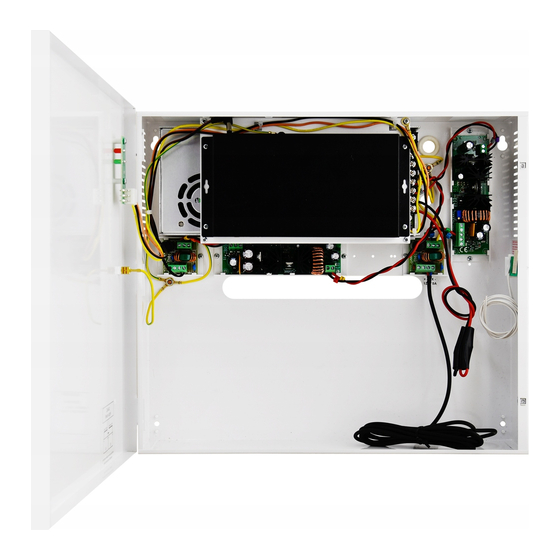
1.3 Description of components and connectors. Fig. 2. The enclosure view. Table 1. ( See Fig . 2) Component No. Description (Fig. 2) Switch PoE Switch mode buffer power supply unit DC/DC50SD converter DC/DC52230 converter Output filter Tamper – micro switch (terminals) of tamper protection (NC) Battery space for two (2 x 17Ah/12V - connect the batteries in series) Power supply connector of the PSU –... -
Page 4: Technical Parameters
Fig. 3. The view of the switch. Table 2. (See Fig.3) Component No Description (Fig. 3) 8 x PoE ports (1÷8) 2 x UPLINK port 52V DC power supply socket 1.4 Technical parameters - parameters of the switch (tab.3) - electrical parameters (tab.4) - mechanical parameters (tab.5) - operation safety (tab.6) - operating parameters (tab.7) - Page 5 105% ÷ 150% of power supply, manual restart Short-circuit protection SCP and overload protection OLP (the fault requires disconnection of the DC output circuit) PSU current consumption 300mA/27,6V Battery charge current 1,0A max. /2x17Ah (+/-5%) Approximate backup time 3h 15min Battery circuit protection SCP and reverse melting fuse polarity connection...
-
Page 6: Installation
2. Installation 2.1. Requirements The device should be mounted by a qualified installer, holding relevant permits and licenses (applicable and required for a given country) for 230V AC and low-voltage installations. The device shall be mounted in confined spaces, according to the environment class II, with normal air humidity (RH=90% max. -
Page 7: Indication Of The Device Operation
Connection schemes 3. Indication of the device operation. 3.1 LED indication of operating status. The PSU is equipped with two diodes on the front panel: RED LED: on – the PSU is supplied with 230V AC off – no 230V AC supply ... -
Page 8: Optical Indication Of The Switch Operation
ON - the switch is powered, correct operation YELLOW LED LIGHT (LINK) OFF- no data transmission The connection status of ON - the device is connected 10/100Mb/s LAN devices, 10/100 Mb/s Blinking – data transmission and data transmission Installation example of the S108-BR battery (Battery not included) -
Page 9: Operation And Use
4. Operation and use. 4.1 Overload or short circuit of the PSU output (SCP on). In case of overload, the output voltage is automatically shut off, and so is the LED indicator. The restoration of the voltage takes place immediately after the failure (overload) is over. 4.2 Disconnection of discharged battery. - Page 10 The power supply unit is adapted for a sealed lead-acid battery (SLA). After the operation period it must not be disposed of but recycled according to the applicable law. Pulsar Siedlec 150, 32-744 Łapczyca, Poland Tel. (+48) 14-610-19-40, Fax. (+48) 14-610-19-50 e-mail: biuro@pulsar.pl, sales@pulsar.pl http:// www.pulsar.pl, www.zasilacze.pl...
Need help?
Do you have a question about the S108-BR and is the answer not in the manual?
Questions and answers