
Subscribe to Our Youtube Channel
Related Manuals for King Industrial KC-117C


Summary of Contents for King Industrial KC-117C
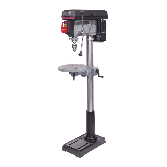
- Page 1 KING CANADA 16 SPEED DRILL PRESS BENCH OR FLOOR MODEL MODELS: KC-117C (BENCH MODEL) KC-117FC (FLOOR MODEL) INSTRUCTION MANUAL COPYRIGHT © 2000 ALL RIGHTS RESERVED BY KING CANADA TOOLS INC.
- Page 2 IMPORTANT INFORMATION 2-YEAR KING CANADA TOOLS LIMITED WARRANTY OFFERS A 2-YEAR LIMITED WARRANTY FOR THIS DRILL PRESS FOR NON-COMMERCIAL USE. PROOF OF PURCHASE Please keep your dated proof of purchase for warranty and servicing purposes. REPLACEMENT PARTS Replacement parts for this tool are available at our authorized KING CANADA service centers across Canada. For servicing, contact or return to the retailer where you purchased your product along with your proof of purchase.
-
Page 3: Specific Safety Rules For Drill Press
GENERAL SAFETY RULES FOR POWER TOOLS 1. KNOW YOUR TOOL 12. ALWAYS WEAR SAFETY GLASSES. Read and understand the owners manual and labels affixed to Always wear safety glasses (ANSI Z87.1). Everyday the tool. Learn its application and limitations as well as its eyeglasses only have impact resistant lenses, they are NOT specific potential hazards. -
Page 4: Specifications
SPECIFICATIONS SPECIFICATIONS FOR 15” MODELS (KC-117C, KC-117FC) VOLTAGE ............................................110V AMPS ..............................................10.5A MOTOR R.P.M..........................................1700 Hz ................................................60 PHASE ..............................................1 CHUCK CAPACITY ........................................5/8” SPINDLE TAPER ..........................................MT#2 NUMBER OF SPEEDS ........................................16... -
Page 5: Getting To Know Your Drill Press
GETTING TO KNOW YOUR DRILL PRESS FIGURE LOCATION AND FUNCTION OF CONTROLS 1. Belt tension lock handles...Tightening handles locks motor 10. Light “ON-OFF” Switch...Turns the light on and off. bracket support to maintain correct belt distance and tension. 11. Depth scale lock...Locks the depth scale at the selected depth. 2. -
Page 6: Tools Needed
UNPACKING/TOOLS NEEDED TABLE OF BOX CONTENTS TOOLS NEEDED A- Head assembly ................1 1- Combination square B- Table ....................1 1- 8” Ajustable wrench C- Column and table support ............1 1- Medium Phillips screwdriver D- Base....................1 E- Box of loose parts ................1 WARNING! To avoid injury from unexpected starting or F- Bag of loose parts ................1 electrical shock, never connect the plug to an outlet until all the... -
Page 7: Electrical Connections
ELECTRICAL CONNECTIONS WARNING ALL ELECTRICAL CONNECTIONS MUST BE DONE BY A QUALIFIED ELECTRICIAN. FAILURE TO COMPLY MAY RESULT IN SERIOUS INJURY!ALL ADJUSTMENTS OR REPAIRS MUST BE DONE WITH THE DRILL PRESS DISCONNECTED FROM THE POWER SOURCE. FAILURE TO COMPLY MAY RESULT IN SERIOUS INJURY! PROPERLY GROUNDED OUTLET POWER SUPPLY WARNING: YOUR DRILL PRESS MUST BE CONNECTED TO... - Page 8 ASSEMBLY INSTRUCTIONS BASE AND COLUMN ASSEMBLY (FIG.6) Column 1. Position the base on the floor. Remove the protective covering and discard. 2. Remove protective sleeve from the column and discard. Place the column assembly on the base, align the holes in the column support Base with the holes in the base.
-
Page 9: Pulley Alignment And Speed Adjustment
ASSEMBLY INSTRUCTIONS INSTALLING THE HEAD (FIG.11) Head locking 1. Remove the protective covering from the head assembly. set screws 2. Carefully lift the head above the column and slide it down on the column as far as it will go. Align the head with the table and the base. -
Page 10: Installing The Chuck
ASSEMBLY INSTRUCTIONS INSTALLING THE CHUCK 1. Clean out the tapered hole in the chuck, clean the spindle nose with Quill a clean cloth. Make sure there are no foreign particles sticking to the surfaces. The slightest piece of dirt on the spindle nose or on the Arbor chuck will prevent the chuck from seating properly. - Page 11 ADJUSTMENTS ADJUSTING THE TABLE SQUARE TO THE HEAD NOTE: The combination square must be “true”. 1. Insert precision round steel rod or straight drill bit approximately 3” long into the chuck and tighten. 2. With the table raised to work height and locked to the column, place the combination square flat on the table beside the rod or drill bit.(Fig.19).
- Page 12 AJUSTEMENTS & OPERATIONS Depth scale lock LOCKING CHUCK AT DESIRED DEPTH 1. With the switch off, loosen the depth scale lock. 2. Turn the feed handles until the chuck is at the desired height. Hold the feed handles at this position. 3.
-
Page 13: Tilting Table
ADJUSTMENTS & OPERATIONS TILTING TABLE To use the table in a bevel (tilted) position (Fig.26), loosen the set 10. Proper tension is achieved when the quill returns gently to the screw under the table bevel lock with a 3mm hex. key. Loosen bevel full up position when released from 3/4”... -
Page 14: Maintenance & Troubleshooting
MAINTENANCE / TROUBLESHOOTING LUBRICATION All of the ball bearings are packed with grease at the factory. They require no further lubrication. Periodically lubricate the splines (Grooves) in the spindle and the rack (Teeth of the quill). WARNING! For your own safety, turn the switch “OFF” and remove the plug from the power source before maintaining or lubricating your drill press. - Page 15 INSTRUCTIONS FOR DUAL LASER GUIDE SYSTEM USING/ADJUSTING DUAL LASER GUIDE SYSTEM WARNING! Do not look directly at the laser beams. Do not aim the laser beams at any person or any object other than your workpiece. Do not deliberately aim the beams into the eye of a person for any length of time. Do not use the laser guide system aimed at a reflective workpiece, wood or rough coated surfaces are acceptable.
Need help?
Do you have a question about the KC-117C and is the answer not in the manual?
Questions and answers