Table of Contents
Advertisement
Quick Links
Download this manual
See also:
User Manual
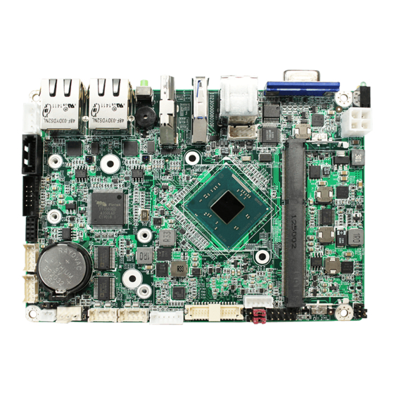
EmCORE-i2305
Form Factor
3.5" Compact Board
I/O
SATA/ mSATA/ USB/
COM/ DIO/ I2C
♦ Technical Support
If you have any technical difficulties, please consult the user's manual first at:
http://www.arbor-technology.com
Contact our customer service at the following addresses if your problem persists.
E-mail: info@arbor.com.tw
♦ Declaration of Conformity
FCC Class A
This device complies with Part 15 of the FCC Rules. Operation is subject to the following two
conditions : (1) this device may not cause harmful interference, and (2) this device must accept
any interference received, including interference that may cause undesired operation.
Copyright® All Rights Reserved.
CPU
®
Intel
Atom™ Processor
E3800 family & Celeron
Processor N-Series
LAN
2 x Realtek® RTL8111
PCIe GbE controllers
- 1 -
3.5" Compact Board
Quick Installation Guide
Video
Dual Channel 24-bit
LVDS, Analog RGB,
®
Vertical HDMI
Audio
Realtek ALC662 HD Audio
CODEC, MIC-in/ Line-out/
Line-in
4041230500120P
Version 1.2
Advertisement
Table of Contents

Related Manuals for Arbor Technology EmCORE-i2305


Summary of Contents for Arbor Technology EmCORE-i2305
-
Page 1: Quick Installation Guide
EmCORE-i2305 3.5" Compact Board Quick Installation Guide Version 1.2 Form Factor Video 3.5" Compact Board Dual Channel 24-bit ® Intel Atom™ Processor LVDS, Analog RGB, ® E3800 family & Celeron Vertical HDMI Processor N-Series Audio SATA/ mSATA/ USB/ 2 x Realtek® RTL8111... -
Page 2: Packing List
Packing List Before starting with the installation, make sure the following items are shipped: 1 x EmCORE-i2305 3.5" Compact Board with heatsink 1 x Driver CD 1 x Quick Installation Guide If any of the aforelisted items is damaged or missing, contact your vendor immediately. - Page 3 Find Device Drivers on CD Windows 7 Device Driver Path \Audio\32bit_Win7_Win8_Win81_R275 Audio \Audio\64bit_Win7_Win8_Win81_R275 Chipset \Chipset\SetupChipset_10.0.13_PC Ethernet \Ethernet\Realtek\Win7\Install_Win7_7085_05222014 \GPIO\windows 7 32_64\Intel Atom E3800 Win7 IO Drivers_Gold_v1.0 package 501232_ GPIO 20140211 \Graphics\WIN7_32\Intel_EMGD.WIN7_PC_Version_36_15_0_1073 Graphic \Graphics\WIN7_64\Intel_EMGD.WIN7_PC_Version_37_15_0_1073 \TXE\Installers (Only for 64-bit) USB3.0 \USB3.0\Intel(R) USB 3.0 eXtensible Host Controller_Win7_32bit_64bit_R3.0.0.33 Serial IO \Serial IO\Intel Processor IO Drivers_Win7_32bit_64bit_Gold_v2.0 Windows 8.1...
- Page 4 Board Dimensions (SKU-E3825) 101.96 98.58 3.38 3.38 98.58 Unit: mm - 4 -...
- Page 5 Board Dimensions (SKU-E3845) 101.96 98.58 3.38 3.38 98.58 Unit: mm - 5 -...
-
Page 6: Specifications
Specifications Form Factor 3.5" Compact Board Soldered onboard Intel® Atom™ Processor E3825 dual-core 1.33GHz, E3845 quad-core 1.91GHz, Celeron® N2807 dual-core 1.58GHz or N2930 quad-core 1.83GHz System Memory 1 x DDR3L SO-DIMM socket, supporting SDRAM up to 8GB Graphics Chipset Integrated Intel® HD Graphics HDMI Vertical HDMI connector Graphics Interface... -
Page 7: Jumper Description
Jumpers & Connectors Quick Reference Jumpers Jumper Description JPIC1 Sets the AT/ATX mode JINV1 Sets the LCD inverter voltage JVLCD1 Sets the power voltage for LVDS1 LCD. JBAT1 Clears/keeps CMOS JRS1 Sets the data transmitting signals for COM2 between RS-232, and RS-485. Connectors Connector Description... -
Page 8: Jumper And Connector Locations
Jumper & Connector Locations INV1 12VIN1 ❶ JPIC1 20 SYSLED1 VGA1 72 74 22 JFRT1 71 73 ❷ JINV1 18 USB1 ❸ JVLCD1 17 USB3 LVDS1 16 USB2 15 HDMI1 KBMS1 14 RES1 COM1&2 13 LAN2 ❹ JBAT1 FAN1 LAN1 ❺... - Page 9 Board Bottom - 9 -...
- Page 10 Jumpers Connectors ➊ ➀ JPIC1: Sets the AT/ATX mode INV1: LCD inverter connector Connector type: 2.00mm pitch 1x5-pin box wafer Jumper type: 2.00mm pitch 2x3-pin header connector Description Pin Description on/off ATX (default) Brightness control ➋ JINV1: Sets the LCD inverter voltage ②...
- Page 11 ➈ ④ AUDIO1: Audio connector COM1&2: Serial port connector Connector type: 2.00mm pitch 2x5-pin wafer connector Connector type: 2.00mm pitch 2x5-pin headers Pin Description Pin Description Description Description DCD# Line Left In Line Right In DTR# DSR# MIC1 MIC2 CTS# RTS# 10 N/C Line-out Left...
- Page 12 ⑯ USB2: USB 3.0 connector JFRT1:Provides connectors to front-panel status LED and toggles. Connector type: USB 3.0/2.0 type-A connectors Connector type: 2.54mm pitch 2x5-pin header The pin assignments conform to Pin Description Pin Description the industry standard. 1 RESET+ RESET- 3 PLED+ PLED- 5 HLED+...
Need help?
Do you have a question about the EmCORE-i2305 and is the answer not in the manual?
Questions and answers