Table of Contents
Advertisement
Quick Links
Our company network supports you worldwide with offices in Germany, Austria,
Switzerland, Great Britain and the USA. For more information please contact:
FORTEC Elektronik AG
Hauptniederlassung
Lechwiesenstr. 9
86899 Landsberg am Lech
Telefon:
+49 (0) 8191 91172-0
Telefax:
+49 (0) 8191 21770
E-Mail:
sales@fortecag.de
Internet:
www.fortecag.de
FORTEC Elektronik AG
Büro Wien
Nuschinggasse 12
A-1230 Wien
Telefon:
+43 1 8673492-0
Telefax:
+43 1 8673492-26
E-Mail:
office@fortec.at
Internet:
www.fortec.at
The information contained in this document has been carefully researched and is, to the best
of our knowledge, accurate. However, we assume no liability for any product failures or
damages, immediate or consequential, resulting from the use of the information provided
herein. Our products are not intended for use in systems in which failures of product could
result in personal injury. All trademarks mentioned herein are property of their respective
owners. All specifications are subject to change without notice.
Manual
AMS100-807
iBASE
FORTEC Elektronik AG
Büro West
Hohenstaufenring 55
50674 Köln
Telefon:
+49 (0) 221 272 273-0
Telefax:
+49 (0) 221 272 273-10
E-Mail:
west@fortecag.de
Internet:
www.fortecag.de
ALTRAC AG
(Tochter der FORTEC):
Bahnhofstraße 3
CH-5436 Würenlos
Telefon:
+41 (0) 44 7446111
Telefax:
+41 (0) 44 7446161
E-Mail:
info@altrac.ch
Internet:
www.altrac.ch
Advertisement
Table of Contents

Related Manuals for IBASE Technology AMS100-807


Summary of Contents for IBASE Technology AMS100-807
- Page 1 Manual AMS100-807 iBASE Our company network supports you worldwide with offices in Germany, Austria, Switzerland, Great Britain and the USA. For more information please contact: FORTEC Elektronik AG FORTEC Elektronik AG Hauptniederlassung Büro West Lechwiesenstr. 9 Hohenstaufenring 55 86899 Landsberg am Lech 50674 Köln...
- Page 2 AMS100-807 Series Fanless System Users Manual Version 1.0...
-
Page 3: Table Of Contents
Table of Contents Chapter 1 Specifications ........................3 Chapter 2 AMS100-807 Series Features..................4 Chapter 3 System Dimensions ......................5 Chapter 4 Opening the Chassis ....................... 6 Chapter 5 Installing the Memory Module ..................6 Installing the 2.5” HDD..................... 7... -
Page 4: Safety Information
Safety Information AMS100-807 is designed and tested to meet the latest standards of safety for information technology equipment. However, to ensure your safety, it is important that you read the following safety instructions. Setting up your system • Read and follow all instructions in the documentation before you operate your system. -
Page 5: Specifications
Standard Full Height Slot opening on Front panel supports add-on card Expansion Slot length up to 122 mm Dimensions 252 (W) x 162 (D) x 64 (H) mm 0 ~ 45℃ Operation Temperature -20 ~ 70℃ Storage Temperature 5% ~ 90% @ 45℃, non-condensing Operation Humidity AMS100-807 Series User’s Manual... -
Page 6: Ams100-807 Series Features
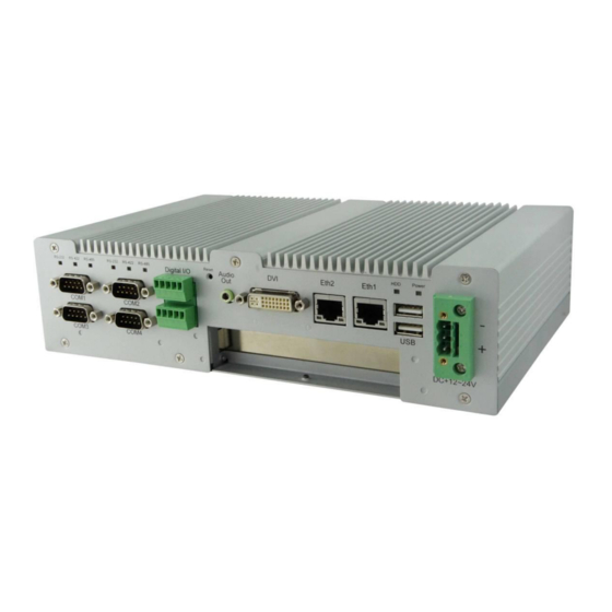
3-pin terminal block or DC Jack +12V ~ +24V DC power input selection Mini PCI-E slot x1 CFast Card slot x1 Supports PCI (IP807) or PCI-E (IP808) Riser Card Supports iSMART feature EuP / ErP compliant Fanless design AMS100-807 Series User’s Manual... -
Page 7: Chapter 3 System Dimensions
Chapter 3 System Dimensions Unit: mm AMS100-807 Series User’s Manual... -
Page 8: Opening The Chassis
Fig. 4-1 Loosen three #6-32 screws on front panel. Fig. 4-2 Loosen Four M3 screws on rear & top panel. Top screw is shorter. Fig. 4-3 The system Chapter 5 Installing the Memory Module Fig. 5-1 Insert DDR3 SO-DIMM memory module. AMS100-807 Series User’s Manual... -
Page 9: Installing The 2.5" Hdd
Fig. 6-1 Loosen four screws to remove HDD Fig. 6-2 Insert the SATA cable bracket. Fig. 6-3 Put HDD on the bracket Fig. 6-4 Assemble cable and HDD shoulder screw Fig. 6-5 Fasten HDD on bracket with four shoulder screws. AMS100-807 Series User’s Manual... -
Page 10: Installing The Mini Pci-E Module
Installing the Mini PCI-e Module Fig. 7-1 Insert Mini PCI-E module and fixed with two M2 screws. Chapter 8 Terminal Block (TB) DC Input Cathode Anode Ground Fig. 8-1 Screw tight the DC cables. Fig. 8-2 Plug TB onto AMS100-807. AMS100-807 Series User’s Manual... -
Page 11: Chapter 9 Rear Usb Cable
Chapter 10 Rear COM 5 & COM6 Cable (Optional) COM 5 & 6 cable Fig. 10-1 Knock off two DB-9 opening and screw Fig. 10-2 Plug COM 5 & COM 6 cable onto the RS-232 connectors on chassis. motherboard. AMS100-807 Series User’s Manual... -
Page 12: Chapter 11 Installing The Add-On Card
Fig. 11-1 Make sure the add-on card interface. Fig. 11-2 Loosen slot screw. Fig. 11-3 Remove HDD kit. Fig. 11-4 Insert add-on card and fasten the screw. Fig. 11-5 Assemble HDD and make sure the guide rail fits the add-on card. AMS100-807 Series User’s Manual... -
Page 13: Chapter 12 Assembling Mounting Brackets
Chapter 13 Optional COM7 & COM8 Assembly Fig. 13-1 IBD-182V, IBASE RS-232 Mini PCI-E card Fig. 13-2 Insert IBD-182V and fixed with two M2 screws. Fig. 13-3 Plug COM port cables onto IBD-182V Fig. 13-4 COM7 & COM 8 AMS100-807 Series User’s Manual... - Page 14 Our company network supports you worldwide with offices in Germany, Austria, Switzerland, Great Britain and the USA. For more information please contact: FORTEC Elektronik AG FORTEC Elektronik AG Hauptniederlassung Büro West Lechwiesenstr. 9 Hohenstaufenring 55 86899 Landsberg am Lech 50674 Köln Telefon: +49 (0) 8191 91172-0 Telefon:...
Need help?
Do you have a question about the AMS100-807 and is the answer not in the manual?
Questions and answers