Table of Contents
Advertisement
Quick Links
AY-x20 Family
Multi-format Proximity Readers
Installation Manual
1. Introduction
The AY-x20 is a family of RFID proximity card readers to be installed for
use with access control systems. The AY-x20 family reads the proximity
card and transmits its data to the access control system, using common
multi-format Wiegand outputs.
1.1
Key Features
Selectable Wiegand 26-Bit, Clock & Data
Reads 26-Bit EM or Rosslare format cards
Waterproof
Green LED control line
Red LED control line
Buzzer Control line
Hold Control line
Optical tamper sensor
Tamper Output line
UV-protected polycarbonate housing
2. Technical Specifications
2.1
Electrical Characteristics
Specification
AY-M20 AY-J20 AY-H20 AY-L20 AY-K20 AY-Q20
Power Supply
Type
Operating
Voltage Range*
Absolute
Maximum (non-
operating)
Current @ 12V
Maximum: 100 mA
Read Range**
(3.9 in.)
Input
Tamper Output
Open collector, active low, max. sink current 16 mA
Maximum Cable
Distance to
Controller
RF Modulation
Bit Rate
* All input voltages should be limited to 1 A maximum. For VAC, the voltage
range is peak-to-peak.
** Measured using a Rosslare proximity card or equivalent. Range also depends
on electrical environment and proximity to metal.
Linear type (recommended)
5–16 VDC
18 VDC
Standby: 85 mA
10 cm
8 cm
(3.2 in.)
(1.6 in.)
Dry Contact, N.O.
150 m (500 ft)
ASK, 125 KHz
106 KHz
AY-M20
2.2
E nvironmental Characteristics
7 B
Specification AY-M20 AY-J20 AY-H20 AY-L20 AY-K20 AY-Q20
Operating
Temp. Range
Operating
Humidity Range
2.3
P hysical Characteristics
8 B
Model
AY-M20
4 cm
AY-J20
AY-H20
AY-L20
AY-K20
AY-Q20
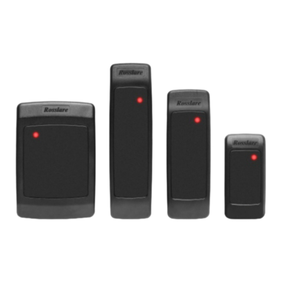
1
Figure 1: AY-x20 Family
AY-L20
AY-J20 AY-K20
AY-H20
-31°C to 63°C (-25°F to 145°F)
0 to 95% (non-condensing)
Dimensions
(H x W x D)
88.9 x 88.9 x 15 mm
(3.5 x 3.5 x 0.6 in.)
120.0 x 42.0 x 14 mm
(4.7 x 1.7 x 0.6 in.)
109.9 x 74.9 x 15 mm
(4.3 x 3.0 x 0.6 in.)
144.9 x 42.9 x 20 mm
(5.7 x 1.7 x 0.8 in.)
79.9 x 39.9 x 12.8 mm
(3.2 x 1.6 x 0.5 in.)
120 x 76 x 20 mm
(4.7 x 3.0 x 0.8 in.)
AY-Q20
Weight
109 g
(3.9 oz.)
88.5 g
(3.1 oz.)
100 g
(3.5 oz)
116 g
(4.1 oz)
70.5 g
(2.5 oz)
480 g
(17.0 oz)
Advertisement
Table of Contents

Related Manuals for Rosslare AY 20 Series


Summary of Contents for Rosslare AY 20 Series
- Page 1 * All input voltages should be limited to 1 A maximum. For VAC, the voltage (4.7 x 3.0 x 0.8 in.) (17.0 oz) range is peak-to-peak. ** Measured using a Rosslare proximity card or equivalent. Range also depends on electrical environment and proximity to metal.
- Page 2 3. Installation Installation Kit 6. Remove the reader's snap-off front cover to reveal the two screw holes (see Figure 2 ). The installation kit consists of the following items to be used during Figure 2: Removing the Top Cover the installation procedure: ...
- Page 3 5. Operation Instructions Testing LED Control Once the reader is wired to a power supply and to the controller, you If the LED control wires (orange and brown) are not used (open), the should test the reader. reader LED remains red continuously, and flashes green momentarily when successfully reading a card.
- Page 4 Consult the dealer or an experienced radio/TV technician for help. Limited Warranty The full ROSSLARE Limited Warranty Statement is available in the Quick Links section on the ROSSLARE website at www.rosslaresecurity.com. Rosslare considers any use of this product as agreement to the Warranty Terms even if you do not review them.
Need help?
Do you have a question about the AY 20 Series and is the answer not in the manual?
Questions and answers