Advertisement
Quick Links
Advertisement

Related Manuals for Hored PS3024S


Summary of Contents for Hored PS3024S
- Page 1 User manual: PS3024S 24 Port Layer 2 PoE Switch...
- Page 2 Installation manual introduction The Product installation manual mainly describes PS3024SPoE switch hardware features, installation methods, and precautions during the installation This manual includes the following chapters: Chapter 1: Product Introduction. Briefly describes the basic features, Detailed hardware & software specifications of the switch and the appearance details.
- Page 3 Chapter 1: Product Introduction 1.1 Products description PS3024S is managed PoE switch for security transmission and WIFI coverage, meet the need of PoE power supply for WIFI AP, IP-camera, WIFI bridge, IP phones and other types of equipment. New generation of high-performance hardware...
- Page 4 1.2 Product Features Full Gigabit Port 16 1000Mbps RJ45 ports (support PoE power supply) with 2 Gigabit SFP ports, Data transmission is not jammed. Realtek chip, the performance is more stable and powerful Realtek high-performance chip can greatly improve network data processing rate Convenient operation ·...
- Page 5 of switches and downloaded PD devices, make operation and maintenance management easy 1.3 product specification Hardware Specifications Chipset RealtekHigh Performance Chipset Flash 16MB 128M DDR Network IEEE 802.3i IEEE 802.3u IEEE 802.3x IEEE 802.3ab IEEE 802.3af IEEE 802.3at Port 2410/100Mbps RJ45 ports 210/100/1000Mbps RJ45 ports 2 Gigabit SFP ports 1 Console port...
- Page 6 Performance Forwarding mode: store and forward Switch Volume (Full-duplex) : 8.8Gbps Packet forwarding rate:6.55Mpps 8K MAC address table lightning protection ±6KV No barrier: ±6KV Air:±8KV Input 100-240V/50-60Hz Dimension 440mm×180mm×44mm (L×W×H) Software Specifications IEEE 802.3: Ethernet Media Access Control (MAC) protocol IEEE 802.3i:10BASE-T Ethernet IEEE 802.3u:100BASE-TX fast Ethernet IEEE 802.3ab:1000BASE-T gigabit...
- Page 7 IEEE 802.1q:VLAN Bridge operation IEEE 802.1d:STP spanning tree IEEE 802.1s:MSTP spanning tree IEEE 802.1w:RSTP spanning tree IEEE 802.3af IEEE 802.3at One key VLAN One key Exnted(1-8 port 250meters PoE Shortcut function distance) One key QoS (Video priority) One key AI power supply DHCP DHCP Snooping Support 4K VLAN...
- Page 8 Support HTTPS、SSL V3、TLS V1、SSH V1/V2 Based on user rating management and password protection Support IP-MAC-PORT Support ARP protection, IP sources protection, DoS protection Support DHCP Snooping、DHCP attack protection Support 802.1X AAA Support port security, port isolation Support CPU protection Support setting the PoE port priority Support viewing POE Chip Status Support setting PoE power supply period...
- Page 9 Support SP、RR、WRR、WFQ Priority scheduling algorithm Support automatically identify, manage and acquire of connected equipment information Support IGMP v1/v2 Snooping Support static multicast Multicast Support multicast VLAN Support multicast filtering, message statistics, unknown multicast discarding Support STP(IEEE 802.1d),RSTP(IEEE 802.1w) and MSTP(IEEE 802.1s) protocol Spanning Tree Support loop protection, BPDU protection...
- Page 10 Supports up to 32 aggregation groups Support IPv6 Ping、IPv6 Tracert、IPv6 IPv6 Telnet Support IPv6 SSH 、IPv6 SSL Support WEB management(HTTP、 HTTPS、SSL V3) Support CLI(Telnet、SSH V1/V2,local serial port) Support SNMP V1/V2/V3 Support LLDP、RMON Management and Support SNMP maintenance Support ARP Protection, IP Source protection、DoS protection Support CPU monitor、memory monitoring...
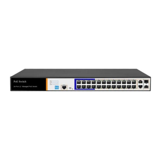
- Page 11 Front Panel Including indicators, RJ45 port, DIP switch, RST button, SFP port, CONSOLE port, as shown below indicator PS3024S The indicator working status is shown as the following table PS3024S The indicator working status is shown as the following table...
-
Page 12: Shortcut Button
POE power Yellow Solid RJ45 port is indicator connected to the powered device and the power supply is normal The corresponding RJ45 port is not connected to the powered device or the power supply is abnormal Blinkin A valid link is LINK/ Connection established... - Page 13 AI power supply: Detect PD, power failure and restart dead equipment RJ45 Port PS3024S with 16 10/100/1000Mbps PoE port, all ports support IEEE802.3af and IEEE802.3at standard PS3024E also provides two 10/100/1000Mbps RJ45 ports as up-link ports, forming a Combo port in SFP1 and SFP2 respectively.
-
Page 14: Console Port
restarting state. When the SYS lamp restarts, the device restarts. When the switch is powered on, press and hold the button for more than 5s to release the button and enter the reset state. When SYS is re-lit, the device is reset successfully ... - Page 15 Chapter2 Hardware connection 2.1 RJ45 port connection Connect the RJ45 port of the switch and the corresponding network device via cables, the POE power supply function of the switch is default enabled on the downlink port of the switch, which can be used for IEEE802.3af or IEEE802.3at standards powered devices such as APs, bridges, and network cameras Note:...
- Page 16 Do not connect the RJ45 port to the phone line 2.2 SFP Port connection PS3024S SFP port only support Gigabit fiber module. Recommended use of standard SFP module products The process of installing a fiber module on a switch is as follows: 1、grasp the optic fiber module from the side, insert it...
- Page 17 Note: DO NOT excessive bending fiber, the radius of curvature should not be lessthan 10cm; Ensure the cleanliness of the fiber surface; Please DO NOT look directly into the optical fiber connector with your eyes as this may cause eye injury 2.3 Check before power on Check whether the outlet power supply meets the switch specifications;...
-
Page 18: Installation Precautions
Port LEDs indicates the connection status of each port, indicating that the switch has started to work normally Chapter3 Installation 3.1 Installation Precautions Note:To avoid improper use of equipment damage and personal injury, please observe the following precautions Installation safety precautions ... - Page 19 power cord and do not wipe it with wet cloth. Do not wash it with liquid Temperature and humidity To ensure the long-term stability working of the switch , please maintain a certain temperature and humidity environment. High or low humidity easily lead to leakage of insulation materials, deformation and even the corrosion of metal parts, the temperature is too high will accelerate the aging process of insulating materials, seriously affecting the...
- Page 20 adsorption, poor contact of the metal contacts. Although the device itself has done some measures in anti-static, but when the static electricity exceeds a certain intensity, it will still cause fatal damage to the electronic components on the internal circuit board. In order to prevent static electricity from affecting the normal operation of the equipment, please note the following:...
- Page 21 Lightning protection When a lightning strike occurs, a strong current will be generated in an instant cause fatal damage to electronic equipment. To achieve better lightning protection, please note the following: 1. Make sure the rack and the ground to maintain good contact;...
-
Page 22: Installation Method
3.2 Installation method standard 19-inch frame PS3024S is designed according to the size of 19-inch standard rack. It can be easily installed on the rack. The specific installation steps are as follows. 1、Check rack grounding and stability;... - Page 23 Note: Good grounding rack is anti-static equipment, anti-leakage, lightning protection, anti-jamming important guarantee, so to ensure that the rack ground wire properly installed; Installation equipment within the rack from the bottom up, to avoid overload installation; Avoid placing other heavy objects on switch to avoid accidents;...
- Page 24 3.3 Web Login Step1、,In the normal operation of the device, connect the computer to the switch's RJ45 port by network cables Step2、 Manually changed the computer IP address to 192.168.254.X (X is 2 ~ 254), subnet mask is 255.255.255.0 Step3、Open computer's browser, type 192.168.254.1 in the address box, hit the Enter key...
- Page 25 Step4、 Enter the default username and password “admin” and then click Login Step5、Entered the switch web management interface successfully when you see picture as below, you can begin to configure the switch...
- Page 26 Chapter 4: Packaging and product usage suggestions 4.1 Open the package carefully check the following list Commodity Quantity Description PoE switch 1pcs Power cord 1pcs Optional Bracket 2pcs Fixed on rack mount After-sale Used for after-ale service card service User manual 1pcs Guide users to install switch...
- Page 27 7. Do not use the switch in places with excessive dust and electromagnetic radiation. Do not use the switch in a place with high temperature and no ventilation; 8. Please do not place heavy objects on the switch to avoid accidents;...
Need help?
Do you have a question about the PS3024S and is the answer not in the manual?
Questions and answers