Table of Contents
Advertisement
Quick Links
Advertisement
Table of Contents

Related Manuals for Hored PS3024GS


Summary of Contents for Hored PS3024GS
-
Page 1: User Manual
User manual PS3024GS 24 Port Gigabit Layer 2 PoE Switch... - Page 2 Installation manual introduction The Product installation manual mainly describes PS3024GS PoE switch hardware features, installation methods, and precautions during the installation This manual includes the following chapters: Chapter 1: Product Introduction. Briefly describes the basic features, Detailed hardware & software specifications of the switch and the appearance details.
-
Page 3: Chapter 1: Product Introduction
Chapter 1: Product Introduction 1.1 Products description PS3024GS is managed PoE switch for security transmission and WIFI coverage, meet the need of PoE power supply for WIFI AP, IP-camera, WIFI bridge, IP phones and other types of equipment. New generation of high-performance hardware and software... - Page 4 1.2 Product Features Full Gigabit Port 24 1000Mbps RJ45 ports (support PoE power supply) with 2 Gigabit SFP ports, Data transmission is not jammed. Realtek chip, the performance is more stable and powerful Realtek high-performance chip can greatly improve network data processing rate Convenient operation ·...
-
Page 5: Product Specification
maintenance management easy 1.3 product specification Hardware Specifications Chipset Realtek High Performance Chipset Flash 16MB 128M DDR Network IEEE 802.3i IEEE 802.3u IEEE 802.3x IEEE 802.3ab IEEE 802.3af IEEE 802.3at Port 10/100/1000Mbps RJ45 ports 2 Gigabit SFP ports 1 Console port 24 10/100Mbps RJ45 port support PoE+ Max 250W... -
Page 6: Software Specifications
Switch Volume (Full-duplex) :52Gbps Packet forwarding rate:38.688Mpps 8K MAC address table lightning protection ±6KV No barrier: ±6KV Air:±8KV Input 100-240V/50-60Hz Dimension 440mm×180mm×44mm (L×W×H) Software Specifications IEEE 802.3: Ethernet Media Access Control (MAC) protocol IEEE 802.3i:10BASE-T Ethernet IEEE 802.3u:100BASE-TX fast Ethernet IEEE 802.3ab:1000BASE-T gigabit Ethernet IEEE 802.3z:1000BASE-X gigabit Ethernet (fiber)... - Page 7 IEEE 802.3af IEEE 802.3at One key VLAN One key Exnted(1-8 port 250meters PoE Shortcut function distance) One key QoS (Video priority) One key AI power supply DHCP DHCP Snooping Support 4K VLAN VLAN Support 802.1Q VLAN、Port VLAN、Voice VLAN Comply the IEEE 802.1d standard Support MAC address learning and aging MAC address table automatically...
- Page 8 Support ARP protection, IP sources protection, DoS protection Support DHCP Snooping、DHCP attack protection Support 802.1X AAA Support port security, port isolation Support CPU protection Support setting the PoE port priority Support viewing POE Chip Status Support setting PoE power supply period Support setting port power Support L2(Layer 2)~L4(Layer 4) packet filtering function...
- Page 9 Support multicast VLAN Support multicast filtering, message statistics, unknown multicast discarding Support STP(IEEE 802.1d),RSTP(IEEE 802.1w) and MSTP(IEEE 802.1s) protocol Spanning Tree Support loop protection, BPDU protection Support for multicast suppression Support broadcast suppression Storm suppression Support for unknown unicast suppression Support static aggregation Support dynamic aggregation Link aggregation...
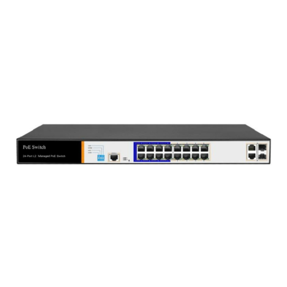
- Page 10 Support SNMP Support ARP Protection, IP Source protection、DoS protection Support CPU monitor、memory monitoring Support system log Support Ping, Tracert detect cable testing 1.4 Appearance Front Panel Including indicators, RJ45 port, DIP switch, RST button, SFP port, CONSOLE port, as shown below...
- Page 11 PS3024GS The indicator working status is shown as the following table PS3024GS The indicator working status is shown as the following table Work Indicators Title Color Description status Solid Power is normal No power, the power Power POWER...
- Page 12 AI power supply: Detect PD, power failure and restart dead equipment RJ45 Port PS3024GS with 16 10/100/1000Mbps PoE port, all port support IEEE802.3af and IEEE802.3at standard SFP Port PS3024GS provides two Gigabit SFP optical module...
- Page 13 expansion slots (25,26), which can be inserted into Gigabit SFP module. RST Button When the switch is powered on, press the button with the needle to release the device and enter the restarting state. When the SYS lamp restarts, the device restarts.
-
Page 14: Chapter2 Hardware Connection
Power socket A 100-240VAC 50/60 Hz power receptacle for accommodating the supplied power cord Ground terminal Please use the grounding wire to prevent lightning. To avoid product lightning strikes and extend product life Chapter2 Hardware connection 2.1 RJ45 port connection Connect the RJ45 port of the switch and the corresponding network device via cables, the POE power supply function of the switch is default enabled on the downlink port of the switch, which can be... - Page 15 Do not connect the RJ45 port to the phone line 2.2 SFP Port connection PS3024GS SFP port only support Gigabit fiber module. Recommended use of standard SFP module products The process of installing a fiber module on a switch is as follows:...
- Page 16 smoothly along the SFP port slot until the optic fiber module and switch are in close contact; Second, confirm the Rx and Tx ports of the fiber module when connecting, insert one end of the fiber into the Rx and Tx ports correspondingly, ensure that the Tx and Rx ends of the interface are connected correctly and the other end of the fiber is connected to another device;...
-
Page 17: Device Initialization
Check whether the switch and other network devices are connected properly 2.4 Device initialization The switch automatically initializes when the power switch is turned on. Indicator will appear the following situation: After the power is turned on, the power indicator remains on, the other indicator is off at this time;... - Page 18 Installation safety precautions The power should be kept off during the installation, while wearing anti-static wrist, and to ensure well touch between anti-static wrist and skin to avoid potential safety hazard; The switch just works normally when it is powered by the ...
- Page 19 Environmental temperature Relative humidity description Working 0℃~40℃ 10%~90% RH no environment condensation Storage -40℃~70℃ 5%~90% RH no environment condensation Altitude Products with this logo are only for safe use in areas below 2000m altitude Dust-proof Dust on the switch surface will cause electrostatic adsorption, poor contact of the metal contacts.
- Page 20 capacitance, inductance and other electronic components by capacitance, inductive coupling, impedance coupling and other conductive, in order to reduce the adverse effects caused by electromagnetic interference, please note the following: 1. Power supply system to take the necessary anti-grid interference measures; 2....
-
Page 21: Installation Method
3.2 Installation method standard 19-inch frame PS3024GS is designed according to the size of 19-inch standard rack. It can be easily installed on the rack. The specific installation steps are as follows. - Page 22 3、place the switch in an appropriate place in the rack and be supported by the bracket. Screw the L-shaped bracket to the guide groove fixed on both ends of the rack to ensure that the switch is stable and horizontally installed on the rack Note:...
- Page 23 3.3 Web Login Step1、,In the normal operation of the device, connect the computer to the switch's RJ45 port by network cables Step2、 Manually changed the computer IP address to 192.168.254.X (X is 2 ~ 254), subnet mask is 255.255.255.0...
- Page 24 Step3、Open computer's browser, type 192.168.254.1 in the address box, hit the Enter key Step4、 Enter the default username and password “admin” and then click Login Step5、Entered the switch web management interface successfully when you see picture as below, you can begin to configure the switch...
- Page 25 Chapter 4: Packaging and product usage suggestions 4.1 Open the package carefully check the following list Commodity Quantity Description PoE switch 1pcs Power cord 1pcs Optional Bracket 2pcs Fixed on rack mount After-sale 1 pcs Used for after-ale service card service User manual 1pcs...
- Page 26 7. Do not use the switch in places with excessive dust and electromagnetic radiation. Do not use the switch in a place with high temperature and no ventilation; 8. Please do not place heavy objects on the switch to avoid accidents;...
Need help?
Do you have a question about the PS3024GS and is the answer not in the manual?
Questions and answers