Advertisement
Quick Links
Advertisement

Related Manuals for Hored S5700-24G-4F-4TF


Summary of Contents for Hored S5700-24G-4F-4TF
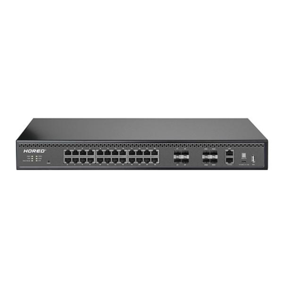
- Page 1 User Manual S5700-24G-4F-4TF 10 Gigabit uplink 24 port Gigabit Layer 3 managed switch...
- Page 2 Installation manual brief introduction "Product Use Guide" introduces S5700- 24G-4F-4TF switch software and hardware parameters , installation methods and matters need attention during the installation process matters. This manual includes the following sections: Chapter 1 : Product introduction. Briefly describe the basic functions and features of the switch, detailed hardware and software specifications, and appearance information.
-
Page 3: Chapter 1 Product Introduction
Chapter 1 Product Introduction 1.1 Product Brief Introduction The S5700- 24G- 4F-4TF uses a new generation of high-performance hardware and software platforms to provide flexible, cost-effective full Gigabit access and uplink ports, support for Layer 3 routing protocols, complete security protection mechanisms, and comprehensive ACL/QoS policies. - Page 4 Broadcom high-end chip, performance is more stable and powerful Broadcom high- end chips, can greatly enhance the network data processing rate Support DHCP Support DHCP server, DHCP relay, DHCP Snooping Support one-stop management of Apollo cloud platform Support cloud platform to visualize management of resources on switches and PD devices, making operation and maintenance management easier 1.3 Product Software and Hardware Specifications...
- Page 5 24 10/100/1000Mbps RJ45 ports 4 10G SFP+ fiber ports 4 1000Mbps RJ45 port(Combo) port 1 RJ45 Console port, 1 1000M RJ45 management port 1 USB 2.0, 1 Mini-usb Console port Forward mode: store and forward Backplane bandwidth: 128 Gbps performance Packet forwarding rate: 95.2 Mpps Support 16 K MAC address...
- Page 6 Lightning ± 6 KV protection Contact : ±6K V air : ±8K V Input power 100-240V/50-60Hz Dimensions (L × 440mm × 320 mm × 44mm W × H) Software features Support RIP V1/V2 , routing OSPFv1/OSPFv2 dynamic routing Support static routing Support DHCP server DHCP Support DHCP relay...
- Page 7 VLAN Support 802.1Q VLAN, MAC VLAN, IP VLAN Voice VLAN Follow the IEEE 802.1d standard MAC address Support MAC address automatic table learning and aging Support static, dynamic, filtering address table Password protection Support user access based on port number, IP address, and MAC address Support HTTPS, SSL V3, TLS V1, SSH V1/V2 Support IP-MAC-PORT ternary...
- Page 8 protection, DoS protection Support DHCP Snooping and DHCP attack protection Support 802.1X authentication, AAA Support port security, port isolation Support CPU protection Access Support L2 (Layer 2) ~ L4 (Layer 4) control (ACL) packet filtering Support port mirroring, port redirection, flow rate limiting, QoS re-marking Support 8 port queues Support port priority, 802.1P priority,...
- Page 9 Supports automatic identification, management, and retrieval of information about attached devices Supports STP (IEEE 802.1d), RSTP (IEEE 802.1w) and MSTP (IEEE 802.1s) Spanning protocols tree Support loop protection, root bridge protection, TC protection, BPDU protection, BPDU filtering Support IGMP v1/v2 Snooping Support fast leave mechanism Multicast Support for multicast VLAN...
- Page 10 Storm Support broadcast suppression suppression Support for unknown unicast suppression Support static aggregation Support dynamic aggregation Link Support IP, MAC, hybrid load aggregation balancing mode Supports up to 32 aggregation groups Support IPv6 Ping, IPv6 Tracert, IPv6 IPv6 Telnet Support IPv6 SSH, IPv6 SSL Support WEB network management (HTTP, HTTPS, SSL V3) Support CLI (Telnet, SSH V1/V2, local...
- Page 11 Support for SNMP V1/V2/V3 Management Support LLDP, RMON Support ARP protection, IP source maintenance protection, DoS protection Support CPU monitoring, memory monitoring Support Apollo cloud platform one-stop management and maintenance Support system log, grading warning Support Ping, Tracert detection, cable detection 1.
- Page 12 Contains indicator light, RJ45 port, SFP port, CONSOLE port , as shown below indicator The S5700-24G-4F-4TF indicator works as shown in the following table. Indicat colo Working name Description or light status Constantl Power on normally Power y bright Indicato...
- Page 13 supply is abnormal The corresponding RJ45 Device flicker port is connected connecti LINK/A gree normally. The corresponding RJ45 indicatio not bright port is not connected properly. The system works flicker normally System gree The system is not indicato working properly and not bright the software is damaged.
- Page 14 RJ45 ports, 4 Combo 10/100/1000 Mbps RJ45 ports, 1 RJ45 Console port, and 1 Gigabit RJ45 management port. SFP port S5700-24G-4F-4TF provides four 10 Gigabit SFP port optical module expansion slots for plugging in Gigabit SFP modules. RST button When the switch is powered on, press the button with the needle and release the device to enter the restart state.
- Page 15 The Console port is used to connect to the serial port of a computer or other terminal to manage or configure the switch. rear panel Includes: power outlet, power switch, ground terminal outlet Connect the power cable to the switch S5700-24G-4F-4TF. The power supply needs to be 100-240V~ 50/60Hz AC power.
- Page 16 2.1 port RJ45 connection Connect the switch and the RJ45 port of the peer network device with a network cable. 2.2 SFP ports connection The SFP port of the S5700-24G-4F-4TF only supports 10 Gigabit fiber modules. Pls use standard SFP module products.
- Page 17 The process of installing a fiber module on a switch is as follows: 1、Grasp the fiber module from the side and insert it smoothly along the SFP port slot of the switch until the fiber module is in close contact with the switch; 2、Confirm the Rx and Tx ports of the fiber module when connecting, insert one end of the fiber into the Rx and Tx ports, ensure that the Tx and Rx ends of the interface are correctly...
-
Page 18: Device Initialization
Ensure the cleanliness of the fiber end face; Please do not look directly into the fiber optic connector with your eyes, as this may cause eye damage. 2.3 Check before power-on Check that the power supply of the power outlet meets the switch specifications. - Page 19 2、The indicator of each port indicates the connection status of each port, indicating that the switch has started to work normally. Chapter 3 product installation 3.1 Installation Precautions Note: To avoid damage to the equipment and personal injury caused by improper use, please observe the following precautions. safety precautions power supply remains off during the installation process.
- Page 20 Before powering on the switch, please make sure that the power circuit is not overloaded, so as not to affect the normal operation of the switch and cause unnecessary damage. To avoid the risk of electric shock, do not open the case while the switch is working, even if it is not charged, do not open it yourself;...
- Page 21 storage temperature / humidity of this series of switches are as follows Environmenta temperat Relative humidity l description working 0°C~40°C 10% to 90% RH does not condense environment Storage -40 ° C ~ 5% to 90% RH does not condense environment 70 °...
- Page 22 device itself has made certain measures in anti-static, when the static electricity exceeds a certain intensity, it will still cause fatal damage to the electronic components on the internal circuit board. To avoid the static electricity affecting the normal operation of the device, please pay attention to the following: 1、Regular dust removal to keep indoor air clean;...
- Page 23 2、The switch should be away from high-frequency, high-power, high-current equipment, such as wireless transmitters; 3、Take electromagnetic shielding measures when necessary. lightning protection needs When a lightning strike occurs, a strong current is generated in an instant, and the air in the discharge path is instantaneously heated to 20,000 degrees Celsius, and an instantaneous large current is enough to cause fatal damage to the electronic device.
- Page 24 3.2 product installation 19 inch standard rack mount The S5700-24G-4F-4TF is designed to fit a 19 -inch standard rack and can be easily mounted to a rack. The specific installation steps are as follows: 1、 Check the grounding and stability of the rack;...
- Page 25 2、 Install the two L -shaped brackets in the accessories on both sides of the switch panel and fix them with the screws provided in the accessories. 3、 the switch is placed in position within the frame, is supported by the carriage; screw the L -shaped bracket fixed to the fixed rack guide slot ends, the switch to ensure a stable, horizontally mounted on the machine frame,...
- Page 26 Note: Good grounding of the rack is an important guarantee for anti-static, anti-leakage, lightning protection and anti-interference of the equipment. Therefore, ensure that the grounding wire of the rack is properly installed. The equipment installed in the rack is generally from bottom to top to avoid overload installation;...
- Page 27 Step2、Manually change the computer IP address to 192.168.254.X (X is within 2~254), and the subnet mask is 255.255.255.0. Step3、Open the browser of the computer, enter 192.168.254.1 in the address box, and hit the Enter key. Step4、 Enter the web network management login page of...
- Page 28 the switch, enter the default username and password admin in the username and password input fields, and then click Login. Step5、You have entered the web management interface of the switch and can start to configure the switch. Chapter 4, packing list and recommendations for use 4.1 Open the package and check the following list carefully.
- Page 29 article Quanti Description switch power cable Switch power supply Hanging ear For rack mounting Warranty For after-sales maintenance Card Product man Used to guide users to install switches 4.2 Suggestions for use 1. For safety reasons, non-professionals should not open the product casing;...
- Page 30 4. Do not use the switch in a humid environment to prevent water from entering the fuselage through the casing, resulting in damage to the machine; 5. Please turn on the power after the line connection is completed; 6. In the state of power-on of the product, please do not plug and unplug the cable at random ;...
Need help?
Do you have a question about the S5700-24G-4F-4TF and is the answer not in the manual?
Questions and answers