Table of Contents
Advertisement
Quick Links
Advertisement
Table of Contents

Related Manuals for Hored S5700-24G-24F-4TF


Summary of Contents for Hored S5700-24G-24F-4TF
- Page 1 User Manual S5700-24G-24F-4TF 10G uplink 48 ports Gigabit Layer 3 Managed Switch...
- Page 2 Installation Manual The 《Product User's Manual》 mainly introduces the software and hardware parameters, installation methods and precautions under the installation process of the S5700-24G-24F-4TF switch. This manual includes the following sections: Chapter 1: Product introduction. Briefly describe the basic features of the switch, detailed hardware and software specifications, and appearance information.
-
Page 3: Chapter 1 Product Introduction
Chapter 1 Product Introduction 1.1 Product introduction The S5700-24G-24F-4TF Layer 3 Stackable Managed Switch is designed for small and medium-sized enterprises (SMEs), large enterprises and Internet Service Providers (ISPs).it is of high performance, flexibility, fault tolerance and advanced software features for maximum return on investment.The S5700-24G-24F-... - Page 4 Broadcom high-level chip, performance more stable and powerful Broadcom high-level chip, greatly improve network data processing rate Support stacking Supports physical stacking:9 switches, virtual stacking :32 switches, and support for ring/daisy chain stacking links Support Apollo cloud platform one-stop management Support cloud platform to visualize management of switches and PDs connected to the PD, making operation and maintenance management easier...
- Page 5 256MB DDR 24 10/100/1000Mbps RJ45 Ports 4 10G SFP Ports Ports 24 10/100/1000Mbps SFP Ports 1 RJ45 Console Port 1 USB 2.0,1 Mini-usb Console Port Forward mode: store and forward Backplane bandwidth:176Gbps Performa Packet forwarding rate:131Mpps Support 16K MAC address table depth Lightning ±6KV...
- Page 6 Size(L× W×H) 440mm×320mm×44mm Software features Support RIP V1/V2,OSPFv1\OSPFv2Dynamic Routing routing Support static routing Support DHCP Server DHCP Support DHCP relay Support DHCP Snooping Support 4KVLAN Support 802.1Q VLAN、MAC VLAN VLAN ,IP VLAN Voice VLAN Based the IEEE 802.1d standard Support MAC address automatic MACAddr learning and aging...
- Page 7 ess table Support static, dynamic, filtering address table Password protection Support user access based on port number, IP address, and MAC address Support HTTPS、SSL V3、TLS V1、 Safety SSH V1/V2 features Support IP-MAC-PORT ternary binding Support ARP protection, IP source protection, DoS protection Support DHCP Snooping and DHCP attack protection Support 802.1X authentication,...
- Page 8 Support CPU protection Support L2 (Layer 2) ~ L4 (Layer 4) packet filtering Support port mirroring, port redirection, flow rate limiting, QoS re-marking Support 8 port queues Support port priority, 802.1P priority, DSCP priority Support SP, WRR, WFQ priority scheduling algorithm Supports automatic identification, management, and achieve information about attached devices...
- Page 9 bridge protection, TC protection, BPDU protection, BPDU filtering Support IGMP v1/v2 Snooping Support fast leave mechanism Multicast Support for multicast VLAN Supports multicast filtering, packet statistics, and unknown multicast discards. Support multicast suppression Storm Support broadcast suppression suppressi Support for unknown unicast suppression Support static aggregation Support dynamic aggregation...
- Page 10 Support IPv6 Ping、IPv6 Tracert、 IPv6 Telnet IPv6 Support IPv6 SSH 、IPv6 SSL Support WEB network management (HTTP, HTTPS, SSL Support CLI (Telnet, SSH V1/V2, local serial port) Manage Support SNMP V1/V2/V3 ment and Support LLDP、RMON maintena Support ARP protection, IP source protection, DoS protection Support Apollo cloud platform one-stop management and...
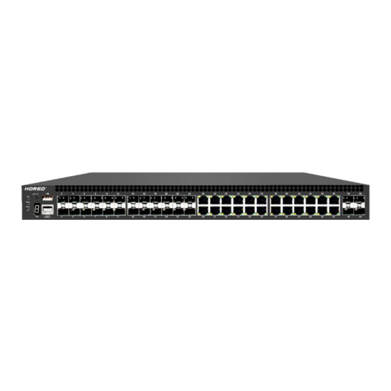
- Page 11 Support Ping, Tracert detection, cable detection 1.4 Appearance Front panel Contains indicator light, RJ45 port, SFP port, as shown below Indicator light S5700-24G-24F-4TF indicator working information is shown in the following table...
- Page 12 Power on normally Power No power, power switch is Indicator not turned on, power supply is abnormal The corresponding RJ45 Device nkli port is connected normally. LINK/A connectio The corresponding RJ45 indication port is not connected properly. nkli The system works normally System indicator The system is not working...
- Page 13 RJ45 Ports S5700-24G-24F-4TF supports 24 10/100/1000Mbps adaptive RJ45 ports SFP Ports S5700-24G-24F-4TF provides 4pcs 10 Gigabit uplink ports, 24 Gigabit SFP optical module expansion slots for plugging into Gigabit SFP modules. RST Button When the switch is powered on, press the button with the needle and release the device to enter the restart state.
-
Page 14: Power Outlet
Back panel Includes: power outlet, power switch, ground terminal Power Outlet The power supply to the switch S5700-24G-24F-4TF must be 100-240V~ 50/60Hz AC power. Ground Terminal Use a wire ground to prevent lightning strikes. To avoid product lightning strikes and extend the life... -
Page 15: Chapter 2 Hardware Connection
2.2 Connect to the SFP port The SFP interface of the S5700-24G-24F-4TF supports 10 Gigabit/Gigabit fiber modules. It is recommended to use standard SFP module products.The process of installing a fiber module on a... - Page 16 switch is as follows: 1、Grab the fiber module from the side and insert it smoothly along the switch SFP port slot until the fiber module is in closer contact with the switch.; 2、Confirm the Rx and Tx ports of the fiber module when connecting.
-
Page 17: Device Initialization
Please do not look directly into the fiber optic connector with your eyes, as this may cause eye damage. 2.3 Check before power-on Check that the power supply of the power outlet meets the switch specifications. Check that the power supply, switch, and rack are properly grounded. -
Page 18: Chapter 3 Product Installation
Chapter 3 Product Installation 3.1 Installation Precautions Note: To avoid damage to the equipment and personal injury caused by improper use, please observe the following precautions. safety precautions power supply remains off during the installation process. Wear an ESD-preventive wrist strap and ensure that the ESD- preventive wrist strap is in good contact with the skin to avoid potential safety hazards. - Page 19 To avoid the risk of electric shock, do not open the case while the switch is working, even if it is not charged, do not open it yourself; Before cleaning the switch, first pull out the power plug of the switch. Do not wipe with a moist fabric. Do not use liquid to clean.
- Page 20 Working 0℃~40℃ 10%~90% RHNon- environment condensing Storage -40℃~70℃ 5%~90% RHNon- environment condensing elevation Products with this mark are only suitable for safe use in areas below 2000m above sea level . dustproof Dust falling on the surface of the switch can cause electrostatic adsorption and poor contact of the metal contacts.
- Page 21 2、Make sure that the equipment is well grounded to ensure the smooth transfer of static electricity. interference Electromagnetic interference will affect the electronic components such as capacitors and inductors inside the device by means of capacitive coupling, inductive coupling, impedance coupling, etc. To reduce the adverse effects caused by electromagnetic interference, please pay attention to the following: 1、The power supply system takes necessary measures...
- Page 22 1、Confirm that the rack is in good contact with the ground; 2、Make sure the power outlet is in good contact with the ground; 3、Reasonable wiring to avoid internal induction lightning; 4、When using outdoor wiring, it is recommended to use a signal lightning arrester.
- Page 23 3.2 Product installation 19 inch standard rack mount The S5700-24G-24F-4TF is designed according to the size of a 19-inch standard rack and can be easily mounted to the rack. The specific installation steps are as follows: 1、Check the grounding and stability of the rack;...
- Page 24 Note: Good grounding of the rack is an important guarantee for anti- static, anti-leakage, lightning protection and anti-interference of the equipment. Therefore, ensure that the grounding wire of the rack is properly installed. The equipment installed in the rack is generally from bottom to top to avoid overload installation;...
- Page 25 3.3 Login management interface Step1、Connect the network cable connected to the computer to the RJ45 port of the switch when the device is working normally. Step2、 manually change the computer IP address to 192.168.254.X (X is 2~254), and the subnet mask: 255.255.255.0...
- Page 26 Step3、Open the computer's browser, enter 192.168.254.1 in the address box, and hit enter Step4、 Enter the Web administrator login interface of the switch, enter the default username and password admin in the input fields of username and password, and then click login Step5、...
-
Page 27: Chapter 4, Packing List And Recommendations For Use
Chapter 4, packing list and recommendations for use 4.1 Open the package and check the following list carefully Article Quantity Description Switch 1pcs Power Cable 1pcs Switch power supply Bracket 2pcs For rack mounting Warranty Card 1pcs For after-sales maintenance Product 1pcs Used to guide users to... - Page 28 manual install switches 4.2 Recommendations 1. For safety reasons, non-professionals should not open the product casing; 2. Pay attention to the danger of strong electricity and safe protection when the product is powered on; 3. Please select the correct power adapter to supply power to the switch.
- Page 29 no ventilation; 8. Please do not place heavy objects on the switch to avoid accidents; 9. It is recommended to use the switch indoors. It is recommended to add a waterproof box when using it outdoors. Note: The pictures in the manual are for reference only, whichever is subject to the actual product.
Need help?
Do you have a question about the S5700-24G-24F-4TF and is the answer not in the manual?
Questions and answers