Advertisement
Quick Links
Advertisement

Related Manuals for Hored PS3016


Summary of Contents for Hored PS3016
- Page 1 User manual PS3016 16 Port Layer 2 PoE Switch...
- Page 2 Installation manual introduction The Product installation manual mainly describes PS3016SPoE switch hardware features, installation methods, and precautions during the installation This manual includes the following chapters: Chapter 1: Product Introduction. Briefly describes the basic features, Detailed hardware & software specifications of the switch and the appearance details.
-
Page 3: Chapter 1: Product Introduction
Chapter 1: Product Introduction 1.1 Products description PS3016S is managed PoE switch for security transmission and WIFI coverage, meet the need of PoE power supply for WIFI AP, IP-camera, WIFI bridge, IP phones and other types of equipment. New generation of high-performance hardware and software platforms are used, providing flexible, cost-effective full Gigabit access and uplink ports, complete security mechanisms, improved ACL / QoS strategy and rich VLAN capabilities. - Page 4 1.2 Product Features Full Gigabit Port 16 1000Mbps RJ45 ports (support PoE power supply) with 2 Gigabit SFP ports, Data transmission is not jammed. Realtek chip, the performance is more stable and powerful Realtek high-performance chip can greatly improve network data processing rate Convenient operation ·...
-
Page 5: Product Specification
maintenance management easy 1.3 product specification Hardware Specifications Chipset RealtekHigh Performance Chipset Flash 16MB 128M DDR Port 16 10/100/1000Mbps RJ45 ports 10/100/1000Mbps RJ45 ports 2 Gigabit SFP ports 1 Console port 16 10/100Mbps RJ45 port support PoE+ Max 150W Single port max 46W LEDs 18 Link/Act LEDs 16 POE LEDs... - Page 6 Input 100-240V/50-60Hz Dimension 440mm×180mm×44mm (L×W×H) Software Specifications IEEE 802.3: Ethernet Media Access Control (MAC) protocol IEEE 802.3i:10BASE-T Ethernet IEEE 802.3u:100BASE-TX fast Ethernet IEEE 802.3ab:1000BASE-T gigabit Ethernet IEEE 802.3z:1000BASE-X gigabit Ethernet (fiber) IEEE 802.3ad: comply link aggregation standard Network standard IEEE 802.3x: flow control IEEE 802.1p: About the traffic priority of the second layer of Qos / Cos protocol (multicast filtering)
- Page 7 One key QoS (Video priority) One key AI power supply DHCP DHCP Snooping Support 4K VLAN VLAN Support 802.1Q VLAN、Port VLAN、Voice VLAN Comply the IEEE 802.1d standard Support MAC address learning and aging MAC address table automatically Support static, dynamic, filter address table Password protection Support based on the port number, IP address, MAC address restrictions on user...
- Page 8 Support 802.1X AAA Support port security, port isolation Support CPU protection Support setting the PoE port priority Support viewing POE Chip Status Support setting PoE power supply period Support setting port power Support L2(Layer 2)~L4(Layer 4) packet filtering function Access control (ACL) Support port mirroring, port redirection, flow rate limit, QoS re-marking Support 8 port queue...
- Page 9 Support STP(IEEE 802.1d),RSTP(IEEE 802.1w) and MSTP(IEEE 802.1s) protocol Spanning Tree Support loop protection, BPDU protection Support for multicast suppression Support broadcast suppression Storm suppression Support for unknown unicast suppression Support static aggregation Support dynamic aggregation Link aggregation Support IP, MAC, hybrid load balancing mode Supports up to 32 aggregation groups IPv6...
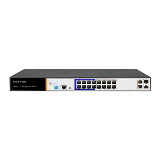
- Page 10 protection、DoS protection Support CPU monitor、memory monitoring Support system log Support Ping, Tracert detect cable testing 1.4 Appearance Front Panel Including indicators, RJ45 port, DIP switch, RST button, SFP port, CONSOLE port, as shown below indicator PS3016S The indicator working status is shown as the following table PS3016S The indicator working status is shown as the...
- Page 11 following table Work Indicators Title Color Description status Solid Power is normal No power, the power Power POWER switch is not turned indicator on, power supply is abnormal The corresponding RJ45 port is connected Solid to the powered device and the power supply is normal power Yellow...
- Page 12 A valid link is Blinkin established on the SFP port Green indicator An invalid link is established on the SFP port Shortcut button QOS: Improve video data processing capabilities and improve the monitoring of Caton and Mosaic phenomena in the network Extend: 1-8 port rate down to 10Mbps, but the transmission distance up to 250 meters VLAN: Isolating ports 1-8 from each other, suppress...
- Page 13 SFP Port PS3016S provides 4 Gigabit SFP optical ports (SFP1, SFP2), can be inserted into the Gigabit SFP module RST Button When the switch is powered on, press the button with the needle to release the device and enter the restarting state.
-
Page 14: Chapter2 Hardware Connection
Power socket A 100-240VAC 50/60 Hz power receptacle for accommodating the supplied power cord Ground terminal Please use the grounding wire to prevent lightning. To avoid product lightning strikes and extend product life Chapter2 Hardware connection 2.1 RJ45 port connection Connect the RJ45 port of the switch and the corresponding network device via cables, the POE power supply function of the switch is default enabled on the downlink port of the switch, which can be... - Page 15 Note: When the switch connected workstations, servers, routers or other ethernet devices the cable length should be within 100 meters; The Auto-MDI / MDIX ethernet interface is enabled by default. Category 5,the standard network cable or crossover cable can be used for Ethernet connection.
- Page 16 2、confirm the Rx and Tx ports of the fiber module when connecting, insert one end of the fiber into the Rx and Tx ports correspondingly, ensure that the Tx and Rx ends of the interface are connected correctly and the other end of the fiber is connected to another device;...
-
Page 17: Device Initialization
2.4 Device initialization The switch automatically initializes when the power switch is turned on. Indicator will appear the following situation: After the power is turned on, the power indicator remains on, the other indicator is off at this time; After about 1 second, all lights except for the power light turn on for about 35 seconds and then turn off;... - Page 18 voltage matches the voltage indicated by the switch Before powering on the switch, make sure that the power circuit is not overloaded, which may affect the normal operation of the switch and even cause unnecessary damage To avoid the risk of electric shock, do not open the case while ...
- Page 19 Altitude Products with this logo are only for safe use in areas below 2000m altitude Dust-proof Dust on the switch surface will cause electrostatic adsorption, poor contact of the metal contacts. Although the device itself has done some measures in anti-static, but when the static electricity exceeds a certain intensity, it will still cause fatal damage to the electronic components on the internal circuit board.
- Page 20 2. Switches should be far away from high-frequency high- power, high-current devices, such as wireless transmitters; 3. If necessary, take electromagnetic shielding measures Lightning protection When a lightning strike occurs, a strong current will be generated in an instant cause fatal damage to electronic equipment.
-
Page 21: Installation Method
wrist strap, fiber optic cable and other tools to prepare your own 3.2 Installation method standard 19-inch frame PS3016S is designed according to the size of 19-inch standard rack. It can be easily installed on the rack. The specific installation steps are as follows. - Page 22 Note: Good grounding rack is anti-static equipment, anti-leakage, lightning protection, anti-jamming important guarantee, so to ensure that the rack ground wire properly installed; Installation equipment within the rack from the bottom up, to avoid overload installation; Avoid placing other heavy objects on switch to avoid accidents; Ensure heat dissipation and air circulation.
- Page 23 Step2、 Manually changed the computer IP address to 192.168.254.X (X is 2 ~ 254), subnet mask is 255.255.255.0 Step3、Open computer's browser, type 192.168.254.1 in the address box, hit the Enter key...
- Page 24 Step4、Enter the default username and password “admin” and then click Login Step5,、Entered the switch web management interface successfully when you see picture as below, you can begin to configure the switch...
- Page 25 Chapter 4: Packaging and product usage suggestions 4.1 Open the package carefully check the following list Commodity Quantity Description PoE switch 1pcs Power cord 1pcs Optional Bracket 2pcs Fixed on rack mount After-sale Used for after-ale service card service User manual 1pcs Guide users to install switch...
- Page 26 7. Do not use the switch in places with excessive dust and electromagnetic radiation. Do not use the switch in a place with high temperature and no ventilation; 8. Please do not place heavy objects on the switch to avoid accidents;...
Need help?
Do you have a question about the PS3016 and is the answer not in the manual?
Questions and answers