Advertisement
Quick Links
Advertisement

Related Manuals for Hored IS104GPS-2F


Summary of Contents for Hored IS104GPS-2F
- Page 1 User Manual IS104GPS-2F 6-port Gigabit managed PoE switch...
- Page 2 Installation Manual Introduction <User Manual> mainly introduces the hardware features, installation methods, and precautions during the installation of IS104GPS-2F. This manual includes the following sections: Chapter 1: Product introduction. Briefly describe the basic functions and features of the switch, detailed hardware and software specifications and appearance information.
-
Page 3: Chapter 1 Product Introduction
IP40 grade, low power design, seismic rail mounting, -40°C-75°C operating temperature, can work in harsh environments; IS104GPS-2F also supports Apollo cloud one-stop management platform for status checking and management monitoring,to make it become a reliable solution for Intelligent transportation, video surveillance and other harsh industrial environments. - Page 4 1.2 Features Full Gigabit Ethernet port 4 full Gigabit RJ45PoE network port, and 2 Gigabit SFP ports, breaking the traditional 100M limitation, data transmission will not stuck Broadcom high performance industrial grade chip for more stable performance Broadcom high-performance industrial-grade chips that dramatically increase network data processing rates...
- Page 5 Support Apollo cloud platform one-stop management Support cloud platform to visualize management of switches and attached power devices, making operation and maintenance management easier 1.3 Software and hardware specifications Hardware specification Broadcom high performance chip Chip 16MB Flash 64MBDDR 4 10/100/1000M RJ45 Port Port 2 1000M SFP Port 410/100/1000MbpsRJ45Port...
- Page 6 6 Link/Act indicator 4POEindicator Indicator ALM Alarm indicator P1、P2 Power Indicator 1 SYS indicator Forward mode: store and forward Backplane bandwidth: 12Gbps Performance Packet forwarding rate: 8.9Mpps Support 8K MAC address table depth IIEEE 802.3: Ethernet Media Access Control (MAC) Protocol IEEE 802.3i: 10BASE-T Ethernet Standard IEEE 802.3u: 100BASE-TX Fast Ethernet...
- Page 7 IEEE 802.3ad: Standard method for performing link aggregation IEEE 802.3x: Flow Control IEEE 802.1p: LAN Layer 2 Qos/Cos protocol for traffic prioritization (multicast filtering) IEEE 802.1q: VLAN Bridge Operation IEEE 802.1d: STP spanning tree IEEE 802.1s: MSTP Spanning Tree IEEE 802.1w: RSTP Spanning Tree IEEE 802.3af IEEE 802.3at EMI:FCCCFR47...
- Page 8 (air) IEC61000-4-3 (RS): 10V/m (80MHz-2GHz) IEC61000-4-4 (EFT): Power Port: ±4kV; Data Port: ±2kV IEC61000-4-5 (Surge): Power Port: ±2kV/DM, ±4kV/CM; Data Port: ±6kV IEC61000-4-6 (CS): 3V (10kHz-150kHz); 10V (150kHz-80MHz) IEC60068-2-6 (Vibration) IEC60068-2-27 (Shock) IEC60068-2-32 (Free Fall) Working temperature: -40 ~ 75 ° C Operation Storage temperature: -40 to 75 °...
- Page 9 Certification CE, FCC, RoHS Mean time between 100,000 hrs failures(MTBF) Warranty 3 years Lightning Network port: ±6KV power port: ±4KV protection Contact: ±8KV Air: ±15KV Input:48-56VDC Housing: IP40 grade protection, corrugated Physical high strength metal housing specification Installation: DIN rail mounting Size:163mm×46.5mm×110mm,Weight:1kg...
- Page 10 Software specification AI PoE AI Loop Protect Global control button AI VLAN AI Extend Hardware Support watchdog Traffic Support Statistics Port energy Support saving DHCP Support DHCP Snooping Support 4KVLANs VLAN Support 802.1QVLAN、MAC VLAN ,IP VLAN Voice VLAN...
- Page 11 Follow the IEEE 802.1d standard Support MAC address automatic learning and MAC address aging Support static, dynamic, filtering address table Password protection Support restrict user access based on port number, IP address, and MAC address Support HTTPS、SSLV3、TLS V1、SSHV1/V2 Support IP-MAC-PORT ternary binding Safety Support ARP protection, IP source protection, DoS features...
- Page 12 Support CPU protection Support PoE power limit Support viewing of PoE chip status management Support to set PoE port priority Support to set PoE power supply time period Support 8 port queues Support port priority, 802.1P priority, DSCP priority Supports SP, WRR, and RR priority scheduling algorithms Supports automatic identification, management and retrieval of information about attached...
- Page 13 Support loop protection, root bridge protection, TC protection, BPDU protection, BPDU filtering SupporIGMPv1/v2 Snooping Support fast leave mechanism Multicast Support multicast VLAN Supports multicast filtering, packet statistics, and unknown multicast discards. Support multicast suppression Storm Support broadcast suppression suppression Support unknown unicast suppression Support static aggregation Link Support dynamic aggregation...
- Page 14 Support IPv6SSH 、IPv6SSL Support network management (HTTP, HTTPS, SSLV3) Support CLI (Telnet, SSHV1/V2, local serial port) Support SNMP V1/V2/V3, Support LLDP、RMON Management Support ARP protection, IP source protection, DoS protection maintenance Support SNMP protocol Support Apollo cloud platform one-stop management and maintenance Support CPU monitoring, memory monitoring Support system log, grading warning Support Ping, Tracert detection, cable detection...
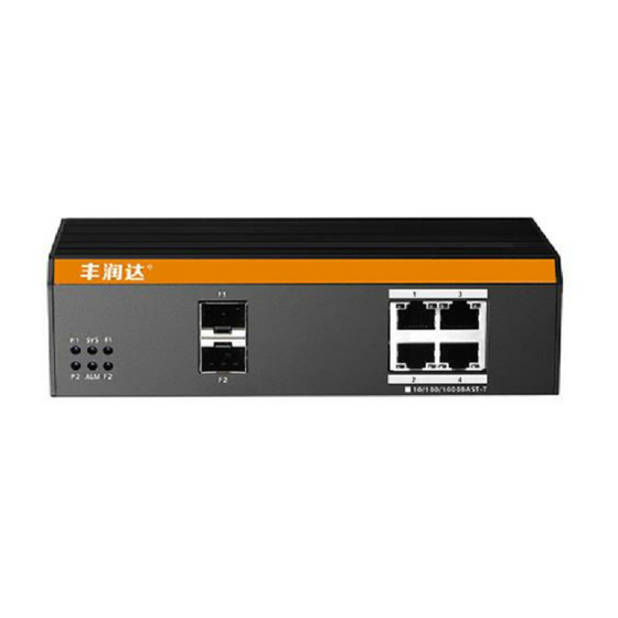
- Page 15 1.4 Appearance Indicator Stat Description The corresponding power supply working P1、P2 normally. The corresponding power supply is not connected or working abnormal. Blink System is running normally...
- Page 16 Off / System operation is abnormal / start alwa unsuccessful brig Alarm start up Alarm not triggered Link/ACT Blink SFP port is working normal F1-F4 SFP port is working abnormally / port is not connected...
-
Page 17: Chapter 2. Hardware Connection
Chapter 2. Hardware Connection 2.1 Connect to RJ45 port Use the network cable to connect the switch to the RJ45 port of network device. Normally, the switch's downlink port has POE power supply enabled by default. It can support POE power supply to AP, bridge, network camera and other PDs which comply with IEEE802.3af and IEEE802.3at standards. - Page 18 2.2 Connect to the SFP port The SFP port of the IS104GPS-2F supports only Gigabit fiber modules. It is recommended to use standard SFP module products. The process of installing a fiber module on a switch is as follows: 1. Grasp the fiber module from the side and insert it smoothly along the SFP port slot of the switch until the fiber module is in close contact with the switch;...
- Page 19 Attention: It is not allowed to excessively bend the fiber, and its radius of curvature should be no less than 10cm; Ensure the cleanliness of the fiber end face; Please do not look directly into the fiber optic connector with your eyes, as this may cause eye damage.
-
Page 20: Chapter 3, Product Installation
and the power switch is turned on. The indicator light will appear as follows: After the power is turned on, the power indicator remains steady, the SYS light enters the blinking state, and the system runs normally. The indicator of each port indicates the connection status of each port, indicating that the switch has started to work normally. - Page 21 installation - Check whether the cable is in place (not more than 100m) according to reasonable configuration requirements. - The product does not provide mounting components, the user must prepare the components of the selected installation type: screws, nuts and tools to ensure reliable installation Power requirements:12-56V DC(12-48V nonsupport PoE,support date exchange only)
- Page 22 5pin 5.08mmterminal Input range:12-56VDC P1&P2 dual redundant power supply, Support reverse connection protection Ground protection Ground protection Connect to ground Rail mounting...
-
Page 23: Chapter 4, Packing List And Use Recommendations
Chapter 4, Packing list and use recommendations 4. 1 Product packaging Item Quantity Description Switch 1 set Phoenix terminal 1*5,1*2 each Connect to power and alarm per one unit switch Warranty card 1 piece For after-sales maintenance User Manual 1 copy Used to guide users to install switches 4.2 Recommendations... - Page 24 3. Do not use the switch in a humid environment to prevent water from entering the fuselage through the casing, resulting in damage to the machine; 4. In the state of power-on of the product, please do not plug and unplug the cable if non special case; 5.
Need help?
Do you have a question about the IS104GPS-2F and is the answer not in the manual?
Questions and answers