Advertisement
Quick Links
Advertisement

Related Manuals for Hored PS2010G


Summary of Contents for Hored PS2010G
- Page 1 User manual PS2010G 8 Port Gigabit Layer 2 PoE Switch...
- Page 2 Installation manual introduction The Product installation manual mainly describes PS2010G PoE switch hardware features, installation methods, and precautions during the installation This manual includes the following chapters: Chapter 1: Product Introduction. Briefly describes the basic features, Detailed hardware & software specifications of the switch and the appearance details.
-
Page 3: Chapter 1: Product Introduction
Chapter 1: Product Introduction 1.1 Products description PS2010G is managed PoE switch for security transmission and WIFI coverage, meet the need of PoE power supply for WIFI AP, IP-camera, WIFI bridge, IP phones and other types of equipment. New generation of high-performance hardware and software... - Page 4 Support a key VLAN, the port 1-8 isolated from each other, which can effectively inhibit network storms, improve network performance Supports IEEE 802.3af / at standard, automatically detects and identifies devices that comply with the IEEE 802.3af / at standard and supply power to it Support Auto MDI/MDIX;...
-
Page 5: Product Specification
Plug and play,no configuration required, easy to use. 1.3 product specification Hardware Specifications Chipset RealtekHigh Performance Chipset Flash 16MB 128DDR Port 8 10/100/1000Mbps RJ45 ports 2 Gigabit SFP fiber ports 1 Console port 8 10/100/1000Mbps RJ45 port support Max 150W Single port max 46W LEDs 10 Link/Act LEDs... - Page 6 Software Specifications IEEE 802.3: Ethernet Media Access Control (MAC) protocol IEEE 802.3i:10BASE-T Ethernet IEEE 802.3u:100BASE-TX fast Ethernet IEEE 802.3ab:1000BASE-T gigabit Ethernet IEEE 802.3z:1000BASE-X gigabit Ethernet (fiber) IEEE 802.3ad: comply link aggregation standard Network standard IEEE 802.3x: flow control IEEE 802.1p: About the traffic priority of the second layer of Qos / Cos protocol (multicast filtering) IEEE 802.1q:VLAN Bridge operation...
- Page 7 Support 4K VLAN VLAN Support 802.1Q VLAN、Port VLAN、Voice VLAN Comply the IEEE 802.1d standard Support MAC address learning and aging MAC address table automatically Support static, dynamic, filter address table Password protection Support based on the port number, IP address, MAC address restrictions on user access Support HTTPS、SSL V3、TLS V1、SSH V1/V2...
- Page 8 Support CPU protection Support setting the PoE port priority Support viewing POE Chip Status Support setting PoE power supply period Support setting port power Support L2(Layer 2)~L4(Layer 4) packet filtering function Access control (ACL) Support port mirroring, port redirection, flow rate limit, QoS re-marking Support 8 port queue Support port priority, 802.1p priority, DSCP priority...
- Page 9 Support broadcast suppression Support for unknown unicast suppression Storm suppression Support static aggregation Support dynamic aggregation Link aggregation Support IP, MAC, hybrid load balancing mode Supports up to 32 aggregation groups Support WEB management(HTTP、 HTTPS、SSL V3) Support CLI(Telnet、local serial port) Support SNMP V1/V2/V3 Support LLDP、RMON Management and...
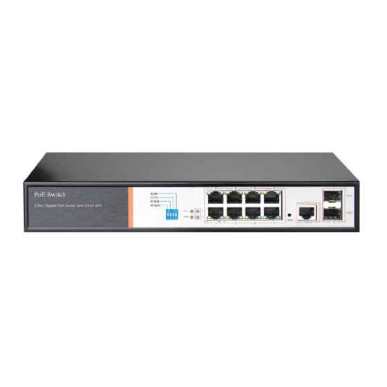
- Page 10 1.4 Appearance Front Panel Including indicators, RJ45 port, DIP switch, RST button, SFP port, CONSOLE port, as shown below indicator PS2010G The indicator working status is shown as the following table Indicators Title Color Description statu Solid Power is normal...
- Page 11 port is connected to the power powered device and the indicat power supply is normal The corresponding RJ45 port is not connected to the powered device or the power supply is abnormal Blink A valid link is Conne established ction LINK/ACT Green indicat...
- Page 12 AI power supply: Detect PD, power failure and restart dead equipment RJ45 Port PS2010G with 8 10/100/1000Mbps PoE port, all ports support IEEE802.3af and IEEE802.3at standard When the switch mode of operation is CCTV mode, 1-8 port can support 250 meters power supply SFP Port ...
- Page 13 enter the reset state. When SYS is re-lit, the device is reset successfully Console port Console port used to connect to computer or other terminal to manage or configure the switch. Back Panel Including: power socket, ground terminal Power socket ...
-
Page 14: Chapter2 Hardware Connection
Chapter2 Hardware connection 2.1 RJ45 port connection Connect the RJ45 port of the switch and the corresponding network device via cables, the POE power supply function of the switch is default enabled on the downlink port of the switch, which can be used for IEEE802.3af or IEEE802.3at standards powered devices such as APs, bridges, and network cameras Note:... - Page 15 Do not connect the RJ45 port to the phone line 2.2 SFP Port connection PS2010G SFP port only support Gigabit fiber module. Recommended use of standard SFP module products The process of installing a fiber module on a switch is as follows:...
-
Page 16: Device Initialization
2.3 Check before power on Check whether the outlet power supply meets the switch specifications; Check the power, switches, racks and other equipment have been properly grounded; Check whether the switch and other network devices are connected properly 2.4 Device initialization The switch automatically initializes when the power switch is turned on. - Page 17 Chapter3 Installation 3.1 Installation Precautions Note:To avoid improper use of equipment damage and personal injury, please observe the following precautions Installation safety precautions The power should be kept off during the installation, while wearing anti-static wrist, and to ensure well touch between anti-static wrist and skin to avoid potential safety hazard;...
- Page 18 High or low humidity easily lead to leakage of insulation materials, deformation and even the corrosion of metal parts, the temperature is too high will accelerate the aging process of insulating materials, seriously affecting the service life of equipment. The normal operation of this series of switches and storage temperature / humidity are as follows Environmental temperature...
- Page 19 1. Regular dust, keep the indoor air clean; 2. Make sure the equipment is well grounded to ensure smooth transfer of static electricity Electromagnetic interference Electromagnetic interference have an impact on the device capacitance, inductance and other electronic components by capacitance, inductive coupling, impedance coupling and other conductive, in order to reduce the adverse effects caused by electromagnetic interference, please note the...
- Page 20 3. Reasonable wiring, to avoid the internal sense ray; 4. Outdoor wiring, it is recommended to use the signal lightning protection device Installation desk requirement Regardless of whether the switch is installed in a rack or on another horizontal workbench, be aware of the following: 1.
- Page 21 3.2 Web Login Step1、In the normal operation of the device, connect the computer to the switch's RJ45 port by network cables Step 2、 Manually changed the computer IP address to 192.168.254.X (X is 2 ~ 254), subnet mask is 255.255.255.0 Step3、Open computer's browser, type 192.168.254.1 in the address box, hit the Enter key...
- Page 22 Step4、 Enter the default username and password “admin” and then click Login Step5、Entered the switch web management interface successfully when you see picture as below, you can begin to configure the switch...
- Page 23 Chapter 4: Packaging and product usage suggestions 4.1 Open the package carefully check the following list Commodity Quantity Description PoE switch 1pcs Power cord 1pcs Optional Bracket 2pcs Fixed on rack mount After-sale Used for after-ale service card service User manual 1pcs Guide users to install switch...
- Page 24 6. When the product is powered on, please do not plug or unplug the cable except for special circumstances. 7. Do not use the switch in places with excessive dust and electromagnetic radiation. Do not use the switch in a place with high temperature and no ventilation;...
Need help?
Do you have a question about the PS2010G and is the answer not in the manual?
Questions and answers