
Related Manuals for Microcom 485TM


Summary of Contents for Microcom 485TM
- Page 1 MODEL 485TM DIRECT THERMAL PRINTER OPERATOR’S MANUAL PART NUMBER: 880063-0100 January 3, 2018 CPC Copyright © 2018 by Microcom Corporation, Lewis Center, Ohio – All rights reserved. Printed in the United States of America...
- Page 3 For this reason, specifications are subject to change without notice. Liability Disclaimer Microcom Corporation makes every effort to assure that all information and specifications contained in this manual are accurate; however, mistakes are sometimes made. Microcom Corporation shall not be liable for any damages resulting in the use or misuse of this product.
-
Page 5: Table Of Contents
3.11.3.1 Entering Diagnostic Mode ............... 3-10 3.11.3.2 Statistics Label ..................3-10 3.11.3.3 Test Ticket ....................3-11 3.12 TOF Sensor 3-11 3.13 Media Roll Holder Option 3-12 3.14 Wristband Media Adapter Option 3-13 3.15 Qualsoft Windows Driver 3-14 485TM Operator’s Manual - 880063-0100... - Page 6 3.16.1.1 Configuration Application - Serial (USB / RS-232) ........3-33 3.16.1.2 Configuration Application - USB HID ............3-34 3.16.1.3 Configuration Application - Ethernet ............3-34 3.16.2 Configuring a device ................... 3-34 3.16.2.1 Applying changes ..................3-35 3.16.2.2 Reverting changes ................... 3-35 485TM Operator’s Manual - 880063-0100...
- Page 7 Replacing the Drive Roller Adjusting Printhead Pressure CHAPTER 5: TROUBLESHOOTING Troubleshooting Tips INDEX General Index List of Figures List of Tables APPENDIX Appendix A: Limited Warranty Appendix B: RMA Procedure Glossary Appendix C: User Notes 485TM Operator’s Manual - 880063-0100...
- Page 8 485TM Operator’s Manual - 880063-0100...
-
Page 9: Introduction
Introduction The Model 485TM printer has been designed to provide solutions for the ticketing industry. The printer uses the same reliable print mechanism found in the Model 428TM and 438TM printers. The print mechanism has been designed with a 4” printhead capable of printing up to 8”... - Page 10 485TM Operator’s Manual - 880063-0100...
-
Page 11: Chapter 1: Printer Specifications
Up to 10”/sec. (250 mm/sec.) 203 DPI = 4.098” (104.10mm); 832 dots Maximum Print Width 300 DPI = 4.252” (108 mm); 1,280 dots Maximum Print Length 26” (660 mm) Minimum Print Length 0.25” (6 mm) Table 1-2 Printing Specifications 485TM Operator’s Manual - 880063-0100... -
Page 12: Media Specifications
Maximum Media Width *NOTE: The printers may print on thicker media types depending on the pliability of the material; however, this requires testing and evaluation. Contact your authorized Microcom Corporation representative for additional information regarding testing and evaluation of thicker or rigid media types. -
Page 13: Chapter 2: Features And Options
· Aztec · EAN 13 · Softstrip · UCC/EAN 128 · QR Code · Postnet. · Rotated: 0 º, 90 º, 180 º, and · Planet Code 270 º. · Expandable in height and width. 485TM Operator’s Manual - 880063-0100... -
Page 14: Special Features
· 300 dpi print head · Heavy Duty Rotary Cutter · Ethernet Port · Pre-Stock Out Sensor Assembly · Low Paper Sensor Assembly · Wristband Option · Paper Supply Holders · Media Catch Trays · Cleaning kit 485TM Operator’s Manual - 880063-0100... -
Page 15: Unpacking And Inspection
Your shipment may contain different items. The foam and shipping container(s) should be kept and used if the printer is to be shipped at a later time. Additional shipping materials can be ordered by contacting the Microcom Corporation Service Department. -
Page 16: Printer Power
RS-232 Serial Cables The printer uses a standard through serial cable, typically referred to as a modem cable, which may be purchased through Microcom Corporation or a local computer supply company. For a 25-pin serial communication port – Use a 25-pin female to 9-pin male cable. -
Page 17: Usb Communication Interface
This driver is supported by both Windows and Linux operating systems through different drivers. The printer may also be configured as a USB HID device so no specific drivers need to be installed. Connecting the printer to the HOST system running Windows will install the printer. 485TM Operator’s Manual - 880063-0100... -
Page 18: Usb Hid
3. To verify the installation, go to the host PC Device Manager and expand the “Ports (COM & LPT) section. One of the COM port should display “Microcom 485 Thermal Printer”. If it does not show up, disconnect the USB cable from the host and then reconnect the cable to reload the driver. -
Page 19: Host Usb Interface
The Draw Kick-out solenoid current must be 1 amp or less to avoid current overloads. This option is only available when using the FGL Emulation mode. Pin 1 - DR1 Pin 2 - DO Pin 3 - DR2 Figure 3-4 Cash Drawer Pin-out 485TM Operator’s Manual - 880063-0100... -
Page 20: Cash Drawer Rj12 Adapter Option
YELLOW BLUE Table 3-2 RJ12 Adapter Pin-out Figure 3-5 Cash Drawer RJ12 Adapter AUX Option The AUX port option or auxiliary port on the printer is for custom application support and for optional sensor support. 485TM Operator’s Manual - 880063-0100... -
Page 21: Loading Media
7. Once the media exits the front of the printer, release the Print Button. Insert media between the guides until resistance is felt Loosen thumb screw to adjust the guide, retighten the thumbscrew when finished Figure 3-6 Loading Media 485TM Operator’s Manual - 880063-0100... -
Page 22: Print Button And Status Indicator Light
Pressing the button twice in Graphics mode will cause the Test Double Press Ticket to print Button Pressed Pressing and holding the button in will cause a line feed in certain and Held In language modes. Table 3-3 Print Button Description 485TM Operator’s Manual - 880063-0100... -
Page 23: Status Indicator Light
Once the error has been cleared, the printer will return to the Ready mode. Pressing the button in this mode will cause the printer to attempt to clear the error and return the printer to Ready mode. 485TM Operator’s Manual - 880063-0100... -
Page 24: Diagnostic Mode
“ON.” Release the Print Button after printer light changes to green. The printer will enter the DIAGNOSTICS Mode, and print the Statistics label and a print test pattern. 3.11.3.2 Statistics Label The Statistics Label may be printed by entering the DIAGNOSTICS Mode. Figure 3-8 Statistics Label Example 3-10 485TM Operator’s Manual - 880063-0100... -
Page 25: Test Ticket
The sensor is set to the maximum detection at the factory. This pot may be used to decrease sensor range to avoid false reflections from stationary objects such as a cutter. 485TM Operator’s Manual - 880063-0100 3-11... -
Page 26: Media Roll Holder Option
The printer may be configured with an optional media holder for media wound on rolls. The holder is designed to hold media cores of 1.5” or larger and contains media guides intended to help prevent unnecessary unwinding of media. Figure 3-11 Rolled Media Holder 3-12 485TM Operator’s Manual - 880063-0100... -
Page 27: Wristband Media Adapter Option
Wristband Guide Loosen locking nut and slide guide into place and retighten into place Insert into media guide making sure that it is flush against the green media guide Figure 3-12 Wristband Media Adapter 485TM Operator’s Manual - 880063-0100 3-13... - Page 28 The printer has some basic requirements in order to operate reliably for years. The printer has some basic requirements in order to operate properly for years. Microcom has a staff that is committed to helping integrate our products. We will do as much as needed to ensure that the process goes correctly and smoothly.
- Page 29 Roll media must be able to turn with minimal resistance and allow the printer to smoothly pull media without jerking or snagging. Minimize friction with the roll holder contact and avoid sharp corners in the media path. Larger, heavier media rolls are 485TM Operator’s Manual - 880063-0100 3-15...
- Page 30 3.15.4 Designing a Roll Support Media roll supports may be purchased from Microcom. If you are designing a custom roll support, please be aware of the following design guidelines. • Implement a simple design which allows the media to be gently placed in the kiosk.
- Page 31 Power supplies sold by Microcom Corporation have gone through rigorous testing to ensure the proper function of the printer. If a non-Microcom supplied power supply is used with the printer, it must comply with the requirements of that printer.
- Page 32 The output circuits (USB, Serial) may not be power limited. Equipment connected to these output connectors shall be of the certified type with their own fire enclosure. If a non- Microcom Corporation supplied power supply is used, it shall be of the certified type and a limited Power Source.
-
Page 33: Qualsoft Windows Driver
The X38 based products use an FTDI based driver while the X85 based products use a Microcom Corporation based driver. The driver requires that the User has ADMIN privileges in order to install the driver. The installation process sample shows the Windows 7 installation. - Page 34 3. Wait for the installer to finish setting up the driver files. 4. Select the New install or Uninstall existing driver if already running a Qualsoft version or if installing more than one printer, select the Install another printer model (Copy n). 3-20 485TM Operator’s Manual - 880063-0100...
- Page 35 Chapter 3 Getting Started 5. Select the Model number of the printer being installed. 6. Select the communication port that is going to be used with the printer. 485TM Operator’s Manual - 880063-0100 3-21...
- Page 36 Getting Started Chapter 3 7. Select next to start the installation. 8. Once the installation is complete, select “Exit” to finish the installation. 9. Select “OK” if prompted to restart and complete the installation. 3-22 485TM Operator’s Manual - 880063-0100...
-
Page 37: Configuring The Driver
This section will explain how to configure the Windows Driver for proper operation. The example below also shows a Microcom Thermal Printer under Unspecified devices. This is the USB driver that is loaded when the printer is powered on and the printer USB port is connected to the printer. -
Page 38: Printer Properties Page - General Tab
This opens the printer properties page. From this screen, Print Test Page may be selected to generate a test page that is sent to the printer. The test page is printed on the media size and type that are specified in the driver preferences. 3-24 485TM Operator’s Manual - 880063-0100... -
Page 39: Printer Properties Page - Ports Tab
Chapter 3 Getting Started 3.16.4 Printer Properties Page - Ports tab Selecting the Ports tab at the top allows the printer port to be changed if connecting to a different printer communication port. 485TM Operator’s Manual - 880063-0100 3-25... -
Page 40: Printing Preferences - About Tab
“About” tab. This shows the driver version number and release date. 3.16.6 Printing Preferences - Print tab The Print tab shows the available options that may be set. Typically, these are already set for proper operation and do not need to be adjusted. 3-26 485TM Operator’s Manual - 880063-0100... -
Page 41: Print Tab - Advanced
3.16.7 Print tab - Halftone Adjustment The Halftone Adjustment icon opens the dialog windows below. This allows the user to manipulate the image settings that the driver uses to produce images. 485TM Operator’s Manual - 880063-0100 3-27... -
Page 42: Print Tab - Halftone Properties
3.16.9 Print tab - User Commands The User commands tab allows for the user to pass printer commands directly into the data stream. This is typically used for either troubleshooting or custom override commands. 3-28 485TM Operator’s Manual - 880063-0100... -
Page 43: Printing Preferences - Paper Tab
New icon to create a form size that matches your media. 3.16.10.4 Paper tab - Mirror Selecting this option will cause the image to appear like it being observed in a mirror. 485TM Operator’s Manual - 880063-0100 3-29... -
Page 44: Paper Tab - Default
Continuous setting instructs the printer to ignore registration marks and will move media based on the form size settings. The Blackline setting cause the printer’s reflective sensor to look for a blackline mark and register based on the other Feed options. The Diecut and 3-30 485TM Operator’s Manual - 880063-0100... -
Page 45: Media Tab - Feed Options
The printer uses its reflective sensor to detect the blackline as the media is passed through the printer and would use its transmissive sensor to detect the blowhole. 485TM Operator’s Manual - 880063-0100 3-31... -
Page 46: Printing Preferences - Presenter Tab
Check with your printer model operator’s manual to see if a presenter is supported. This tab is ignored on models that do not support the use of a presenter. 3-32 485TM Operator’s Manual - 880063-0100... -
Page 47: Presenter Tab - Configuration
This field controls the time that the presenter will present the paper before retracting into the waste bin. 3.16.12.2.2 Configuration - Maximum Present Distance (inch) This is the maximum size that the printer will present when using the enabled mode. This value is in inches. 485TM Operator’s Manual - 880063-0100 3-33... -
Page 48: Configuration - Advanced
The Disable Status checkbox is used to control whether the Port Monitor Status popup window is displayed or not. This is used to get real time status from the printer while printing via the Windows driver. 3-34 485TM Operator’s Manual - 880063-0100... - Page 49 Chapter 3 Getting Started 485TM Operator’s Manual - 880063-0100 3-35...
-
Page 50: Printing Preferences - Save/Restore Tab
This will force the driver defaults of the printer model installed. 3.16.15 Status Messages This section describes the Windows compatible Status messages that are displayed in spooler and the Status Monitor feature found on the Modification tab. These messages may 3-36 485TM Operator’s Manual - 880063-0100... -
Page 51: Printer_Status_User_Interventio N
>HEAD UP< message. 3.16.15.10 PRINTER_STATUS_IO_ACTIVE This message is used to indicate that the optional >INPUT 2< sensor is active. The >INPUT 2< message is the equivalent LDS1 control language printer message that is reported. 485TM Operator’s Manual - 880063-0100 3-37... -
Page 52: Configuration Application
COM port is bound to the Model 485, check the ‘Devices and Printers’ menu in the Windows Control Panel. The printer should be listed as Microcom 485 Thermal Printer (COM#) - choose this same COM device within the 485 Configuration Application to configure the printer using RS-232 or USB serial as the active interface. -
Page 53: Configuration Application - Usb Hid
Microcom 485 as “Microcom - 485 - 123456”. Choose the desired printer from the selection list. If more than one Microcom 485 is connected to your computer and you do not know the serial number, press the push button on the printer to print a test ticket while in FGL mode or a double press while in Graphics mode. -
Page 54: Applying Changes
The Preferences window can be accessed by selecting File->Preferences from the menu bar. Within the preferences you can change the application output directory, gain access to read-only settings (with a password of course), and more. 3-40 485TM Operator’s Manual - 880063-0100... -
Page 55: Table 4-1 Recommended Maintenance Schedule
It is important to note that the optimum print quality and print head life is achieved by maintaining a clean printer and print head. A Microcom Corporation approved cleaning kit (part # 040005-0000) is available; contact your sales representative for purchasing information. -
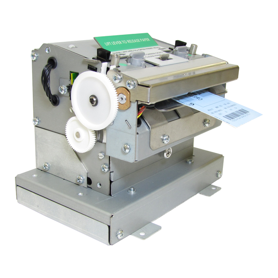
Page 56: Figure 4-1 Releasing The Printhead Assembly
2. Dampen both sides, on one end, of the cleaning card with isopropyl alcohol or use a pre-moistened cleaning card. 3. Release the printhead assembly to insert the cleaning card under the printhead. Figure 4-1 Releasing the Printhead Assembly Figure 4-2 Rotate the Printhead Assembly to the Open Position 485TM Operator’s Manual- 880063-0100... -
Page 57: Figure 4-3 Remove The Cleaning Card
3. Release the printhead assembly and rotate to the open position. 4. The exposed Drive Roller, Printhead, and Paper Path may be cleaned using a cotton swab or lint-free wiping rag dampened with isopropyl alcohol. 485TM Operator’s Manual - 880063-0100... -
Page 58: Figure 4-4 Internal Cleaning
CAUTION: Isopropyl Alcohol or other approved non-Abrasive solution should be used to clean the drive roller. The use of other cleaning solvents or materials is not recommended and may degrade the performance of the drive roller. 485TM Operator’s Manual- 880063-0100... - Page 59 2. Unscrew the Cutter or Tear Assembly using the mounting screw that is located in the bottom center on the front of the Print Mechanism. Cutter Mounting Screw. Figure 4-6 Cutter or Tear Assembly Mounting Screw 485TM Operator’s Manual - 880063-0100...
- Page 60 5. Reattach the cutter or tear assembly taking care to locate the top lip of the assembly to the hook detail in the sheet metal. Hook detail that the cutter or tear assemblies are attached Figure 4-8 Cutter or Tear Assembly Mounting Hook 485TM Operator’s Manual- 880063-0100...
- Page 61 If light print is detected, please adjust your printer’s contrast setting (^D36) and/or verify that the thermal coating on the media is sufficient. Figure 4-9 Narrow Media Light Spring Setting Figure 4-10 Wide Media Heavy Spring Setting 485TM Operator’s Manual - 880063-0100...
- Page 62 Printer Maintenance Chapter 4 485TM Operator’s Manual- 880063-0100...
- Page 63 ü Verify that the media contains some sort of registration mark. ü Verify that the printer is received proper formatting instructions. ü Verify that nothing is blocking the internal registration mark sensors. ü Contact your Service Representative. 485TM Operator’s Manual - 880063-0100...
- Page 64 ü Cycle power to reset the printer. The status indicator light is flashing red in color: ü Generally due to a power fail error. ü Verify that the AC line-voltage is present at the AC outlet. ü Cycle power. 485TM Operator’s Manual - 880063-0100...
- Page 65 Printhead ................................ 4-4 Schedule ................................. 4-1 Thermal Card..............................4-1 Media ................................. 1-2 Maximum Thickness ............................1-2 Maximum Width .............................. 1-2 Specifications ..............................1-2 Types ............................1-2, 7-5, 7-6, 7-7 Media Width ............................... 1-2 Memory ..............................1-1, 7-6, 7-7 485TM Operator’s Manual - 880063-0100...
- Page 66 Media ................................1-2 Printing ................................1-1 SRAM ................................1-1, 7-7 Tag stock ................................7-7 Temperature ................................ 1-1 Thermal Printer Card ............................4-2 Troubleshooting ..............................5-1 TXD ..................................7-7 Unpacking ................................3-1 USB ..................................7-7 Warranty ................................7-1 485TM Operator’s Manual - 880063-0100...
- Page 67 Figure 4-8 Removing the Platen ................4-6 Figure 4-9 Cutter or Tear Assembly Mounting Hook ..........4-7 Figure 4-10 Narrow Media Light Spring Setting ............4-8 Figure 4-11 Wide Media Heavy Spring Setting ............4-8 485TM Operator’s Manual - 880063-0100...
- Page 68 485TM Operator’s Manual - 880063-0100...
- Page 69 Media Specifications ................1-2 Table 3-1 RS-232 Cable Configurations ............... 3-3 Table 3-2 RJ12 Adapter Pin-out ................3-6 Table 3-3 Print Button Description................ 3-8 Table 3-4 Status Indicator Light Description ............3-9 Table 4-1 Recommended Maintenance Schedule..........4-1 485TM Operator’s Manual - 880063-0100...
- Page 70 485TM Operator’s Manual - 880063-0100...
- Page 71 Although the user is not required to purchase Microcom Corporation brand supplies, to the extent it is determined that the use of other supplies (such as non-approved label stock, ribbons, and cleaning solutions) shall have caused any defects in the thermal print head for which the warranty claim has been made, the user shall be responsible for Microcom Corporation’s...
- Page 72 485TM Operator’s Manual - 880063-0100...
- Page 73 Return the defective item(s) for repair to the address listed above, freight and insurance prepaid. Upon receipt of an RMA number, the customer contact will be notified by a Microcom Corporation representative regarding repair charges, at which time the ship method will be determined.
- Page 74 485TM Operator’s Manual - 880063-0100...
- Page 75 DSR (Data Set Ready) - A status signal from the printer (DCE) to the host PC (DTE) telling the PC that the printer is powered up. Used in conjunction with DTR. Microcom Corporation does not use this signal.
- Page 76 DCE end of an RS-232 link. Used in conjunction with DSR. Microcom Corporation does not use this signal. Ethernet - A fast and capable serial interface used by many networks for connecting host computers to various peripherals.
- Page 77 1M bits/second. (Hardly used at all anymore). 2) USB 1.1 transfers at 12M bits/second. (The 324 & 424 printers use this). 3) USB 2.0 transfers at 480M bits/second. (All newer PC’s use this). 485TM Operator’s Manual - 880063-0100...
- Page 78 485TM Operator’s Manual - 880063-0100...
- Page 79 _________________________________________________________________________ _________________________________________________________________________ _________________________________________________________________________ _________________________________________________________________________ _________________________________________________________________________ _________________________________________________________________________ _________________________________________________________________________ _________________________________________________________________________ _________________________________________________________________________ _________________________________________________________________________ _________________________________________________________________________ _________________________________________________________________________ _________________________________________________________________________ _________________________________________________________________________ _________________________________________________________________________ _________________________________________________________________________ _________________________________________________________________________ _________________________________________________________________________ _________________________________________________________________________ _________________________________________________________________________ _________________________________________________________________________ _________________________________________________________________________ _________________________________________________________________________ _________________________________________________________________________ _________________________________________________________________________ _________________________________________________________________________ _________________________________________________________________________ _________________________________________________________________________ _________________________________________________________________________ _________________________________________________________________________ _________________________________________________________________________ _________________________________________________________________________ _________________________________________________________________________ _________________________________________________________________________ _________________________________________________________________________ 485TM Operator’s Manual - 880063-0100...
- Page 80 7-10 485TM Operator’s Manual - 880063-0100...
Need help?
Do you have a question about the 485TM and is the answer not in the manual?
Questions and answers