
Subscribe to Our Youtube Channel
Related Manuals for Scotchman SU-280-G


Summary of Contents for Scotchman SU-280-G
- Page 1 MODEL SU-280-G BAND SAW PRINTED APRIL 2021 SCOTCHMAN INDS. - 180 E US HWY 14 - PO BOX 850 - PHILIP, SD 57567 Call: 1-800-843-8844...
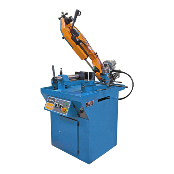
- Page 2 SU-280-G Utility Band Saw...
- Page 3 BEST IN THE BUSINESS WARRANTY WWW.SCOTCHMAN.COM...
-
Page 4: Table Of Contents
Discharge Tracks With Scales 11.0 DRAWINGS AND SCHEMATICS 11.1 Electrical Schematic 11.2 MACHINE EXPLODED VIEW 11.3 Clamp (Exploded View) 11.4 GUIDES (Exploded View) SCOTCHMAN INDS. - 180 E US HWY 14 - PO BOX 850 - PHILIP, SD 57567 Call: 1-800-843-8844 Page 2... -
Page 5: Introduction
1.2 WARRANTY Scotchman Industries, Inc. will, within three years of the date of purchase, replace F.O.B. the factory or refund the purchase price for any goods which are defective in materials or workmanship, provided the buyer, at the seller’s option, returns the defective goods freight and delivery prepaid to the seller,... -
Page 6: General Machine Information
2.0 GENERAL MACHINE INFORMATION 2.1 MACHINE IDENTIFICATION DATA MODEL SERIAL NUMBER YEAR OF MANUFACTURE NOTE: In order to request replacement parts, whether they are covered by the warranty or not, always state the model and serial number of the machine, as well as the name of the part and the code that appear in the last chapter of exploded views. -
Page 7: Transport And Storage
4.0 TRANSPORT & STORAGE In the above drawing, the machine is bolted to a A sling should be placed under the vise casting on pallet before it is lifted or moved with a forklift. the front of the machine (1) and another under the pivot casting (2) toward the rear of the machine. -
Page 8: Connection To The Electric System
5.2 CONNECTION TO THE ELECTRIC SYSTEM Ensure that the power supply voltage corresponds to the voltage on the data plate of the machine. Connect the cable to the electric system, using a plug that is appropriate for the characteristics of the same, thereby respecting color codes. After the machine has been connected, make sure that the rotation of the hydraulic motor matches with the direction indicated by the arrow shown. -
Page 9: Selection Of The Band Saw Blade
5.4 SELECTION OF THE BAND SAW BLADE TO SELECT A BLADE WITH THE PROPER TEETH PER INCH, PLEASE REFER TO THE TABLES BELOW. THE TOP TABLE IS FOR SOLIDS AND THE BOTTOM IS FOR TUBE AND PROFILES. DIMENSIONS ARE SHOWN AS INCH - MM L (INCH - MM) TEETH PER INCH 14/14, 8/12... -
Page 10: Cutting Coolant
5.5 CUTTING COOLANT Use only pure, synthetic water-soluble sawing coolant in this saw. The saw holds 4 gallons. Coolant should be mixed in a ratio of one part coolant to seven parts water. Premixing the coolant before adding to the saw is also recommended. Add through the top of the saw. DO NOT OVER FILL!! CAUTION: When it is necessary to empty the liquid coolant tank, please properly dispose of the old coolant. -
Page 11: Machine Controls
6.2 MACHINE CONTROLS SAW BLADE SWITCH COOLANT START EMERGENCY 3-PHASE SAWS HAVE 2 SPEEDS. SWITCH BUTTON STOP BUTTON SINGLE PHASE SAW HAS 1 SPEED. THE CONTROL PANEL IS LOCATED ON THE FRONT OF THE MACHINE. HANDLE & SWITCH FLOW CONTROL THE SWITCH ON THE HANDLE STARTS FLOW CONTROL IS LOCATED TO THE THE SAW BLADE. -
Page 12: Raising And Lowering The Pivot Stop
6.3 RAISING AND LOWERING THE PIVOT STOP The electric switch (1) is activated when the moving cylindrical stop (2) contacts it. The cylindrical stop should contact the switch first and turn off the saw. The cylindrical stop should then rest on top of the adjustable hard stop (3) that completely stops the downward travel of the saw. -
Page 13: Adjustment Of Cutting Blade Guides
6.4 ADJUSTMENT OF CUTTING BLADE GUIDES In order to obtain a square cut, you must make sure that there is a distance of .035 thousandths of an inch (0.9 mm) between the side guide plates (2), so that they are all in contact with the blade. To adjust this distance the blade must be removed. -
Page 14: Troubleshooting/Corrective Maint
7.0 TROUBLESHOOTING/CORRECTIVE MAINTENANCE PROBLEM POSSIBLE CAUSES Check the incoming power supply. Motor fuse has blown. 2A fuse has blown. (located inside the Control Panel) The machine does not start. Check the operating contactor, start-up control and transformer. (Above located inside the Control Panel) The rear arc guard has not activated the safety micro-switch, or this is not working properly. -
Page 15: Maintenance Schedule
8.0 MAINTENANCE SCHEDULE 8.1 TYPE & FREQUENCY OF MAINTAINENCE LUBRICATION POINTS TYPE OF GREASE/OIL FREQUENCY Bearing grease Yearly Pivot Pin Sect. 11.2 #16 Front and Rear Blade Guides SAE 30 Weekly Bearings Sect. 11.2 Bearing grease Weekly CHECK MATERIALS TO USE FREQUENCY 90-100 BAR (see gauge) Saw blade tension... -
Page 16: Recommendations For Safety, Maintenance, & Repairs
NOTE: In case of any doubt or problem, please call us at the number below. SCOTCHMAN IND. Call: 1-800-843-8844 ATTENTION: The manufacturer hereby guarantees the supply of each one of the parts or components for at least three years from the manufacturing date of the machine. -
Page 17: Accessories
10.0 ACCESSORIES Scotchman has several accessories to help with your sawing needs; the first of which are our Material Supply Tracks. They are available in 5' and 10' lengths and can be assembled to as long as needed. The same is true for our Discharge Tracks. They are available with either our Quick-Loc or Multi-Loc measuring systems, which will save you time and increase your productivity. - Page 18 SCOTCHMAN RG DIGITAL QUICK STOP This Digital Quick Stop is an entry level programmable stop and is available in 8' and 12' lengths. It is priced right, yet very durable. Setup is as easy as entering the desired cut length and pressing go!
-
Page 19: Material Supply Tracks
10.1 MATERIAL SUPPLY TRACKS A 10’ and 20’ roller supply track is an available option for this saw. They can be bolted to the input side of the saw (either the left or right hand side) to support longer pieces of material. If a longer supply track is needed, these can be bolted together, end to end. - Page 20 P/N 029987 - 10' Saw Conv. W/Legs SU-280 LS P/N 029988 - 20' Saw Conv. W/Legs SU-280 LS P/N 029989 - 10' Saw Conv. W/Legs SU-280 RS P/N 029995 - 20' Saw Conv. W/Legs SU-280 RS 028682 REPAC BOX SU-280 LS ITEM PART NUMBER DESCRIPTION...
-
Page 21: Discharge Tracks With Scales
10.2 DISCHARGE TRACKS WITH SCALES Roller discharge tracks, equipped with either a Right or Left-Hand Quick-Loc, are available in 5’ and 10’ lengths. Part numbers are shown on the next page. The discharge tracks allow fast set-up and accuracy for various lengths of cuts. Explained in detail below and shown on the next page is our popular Quick-Loc measuring system mounted to our roller conveyor. - Page 22 P/N 029996 - 5' Saw Conveyor RHE Quick Loc SU-280 Conveyor P/N 029998 - 5' Saw Conveyor LHE Quick Loc SU-280 029232 - RH QUICK-LOC STOP ASS'Y End-Brackets P/N 029990 - 10' Saw Conveyor RHE Quick Loc SU-280 P/N 029992 - 10' Saw Conveyor LHE Quick Loc SU-280 029232 (RH) - Q-L Stop Assembly 029226 - RH Tape...
-
Page 23: Drawings And Schematics
11.0 DRAWINGS & SCHEMATICS 11.1 ELECTRICAL SCHEMATIC THREE PHASE SINGLE PHASE L - N 3,5A (460 V) 5,2A (230 V) 6,5A (230 V) 230/460 - 24V 230/460 - 24V TRAFO 20VA 1L1 1L2 TRAFO 20VA R1 S1 T1 U V W U V W 0,3A (460 V) 2 5 14... - Page 24 Remove a bolt on the left side of the control panel and it will swing out allowing access to the electrical components. FLOW CONTROL VALVE The flow control valve has an electrical solenoid attached to it. The valve and solenoid is located inside the cabinet and is shown SOLENOID in the image on the left.
-
Page 25: Machine Exploded View
11.2 MACHINE EXPLODED VIEW 50 51 EXPLODED VIEW HYDRAULIC DESCENT Page 23... - Page 26 1667 MANUAL END OF TRAVEL 2K28016BH1 HYDR. DOWN REGULATOR SU-280 CHID00RF132 62* - WAS P/N 2K3700R281 12* - Was SHCS SCOTCHMAN INDS. - 180 E US HWY 14 - PO BOX 850 - PHILIP, SD 57567 Call: 1-605-859-2542 Page 24...
-
Page 27: Clamp (Exploded View)
VICE SPRING SU-280 SPRING 2K20000091 M8 X 20 DIN7991 FSHCS 230110 HOOP OF PUSH 2K2600A372 Ø 5X20 ELASTIC PIN TD14810520 SCOTCHMAN INDS. - 180 E US HWY 14 - PO BOX 850 - PHILIP, SD 57567 Call: 1-605-859-2542 Page 25... -
Page 28: Guides (Exploded View)
GUIDE PROTECTOR SU-280 2K28000311 M5 X 10 SHCS TD91205010 M5 X 10 SHCS TD91205010 BEARING 635ZZ 2K2800R001 2K26000701 NYLON BAND SAW PROTECTOR SCOTCHMAN INDS. - 180 E US HWY 14 - PO BOX 850 - PHILIP, SD 57567 Call: 1-605-859-2542 Page 26...
Need help?
Do you have a question about the SU-280-G and is the answer not in the manual?
Questions and answers