Table of Contents
Advertisement
Quick Links
r.LiNK Video inserter
RL3-LR17
Compatible with
Land Rover and Jaguar vehicles
with Incontrol Touch Pro Duo infotainment
and 10.2 inch monitor
Video-inserter for one rear-view camera
and two additional video inputs
Product features
Video-inserter for factory-infotainment systems
1 CVBS Input for rear-view camera
2 CVBS Video-inputs for after-market Video sources (e.g. USB-Player, DVB-T2
Tuner)
Automatic switching to rear-view camera input on engagement of the reverse gear
Activatable parking guide lines for rear-view camera (not available for all vehicles)
Video-in-motion (ONLY for connected video-sources)
Video-inputs NTSC compatible
Version 05.06.2020
HW:CAM(V98)/(V31)
RL3-LR17
Advertisement
Table of Contents

Subscribe to Our Youtube Channel
Related Manuals for NavLinkz RL3-LR17


Summary of Contents for NavLinkz RL3-LR17
- Page 1 Video inserter RL3-LR17 Compatible with Land Rover and Jaguar vehicles with Incontrol Touch Pro Duo infotainment and 10.2 inch monitor Video-inserter for one rear-view camera and two additional video inputs Product features Video-inserter for factory-infotainment systems 1 CVBS Input for rear-view camera ...
-
Page 2: Table Of Contents
Case 2Interface does not receive the reverse gear signal 2.7. Connection - video-interface and external keypad 2.8. Picture settings 3. Interface operation 3.1. By factory touch screen 3.2. By keypad 4. Specifications 5. FAQ – Trouble Shooting-Interface functions 6. Technical support Version 05.06.2020 HW:CAM(V98)/(V31) RL3-LR17... -
Page 3: Prior To Installation
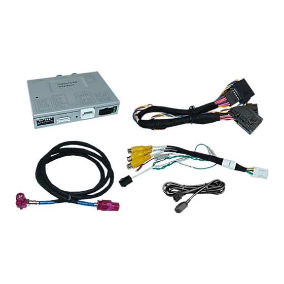
Due to changes in the production of the vehicle manufacturer there’s always a possibility of incompatibility. 1.1. Delivery contents Take down the serial number of the interface and store this manual for support purposes: ____________________ Version 05.06.2020 HW:CAM(V98)/(V31) RL3-LR17... -
Page 4: Checking The Compatibility Of Vehicle And Accessories
To delay the switch-back an additional electronic part is required. Guidelines The display of the guidelines does not work in all vehicles. Video input signal only NTSC compatible Version 05.06.2020 HW:CAM(V98)/(V31) RL3-LR17... -
Page 5: Boxes And Connectors - Video Interface
CVBS Video 2-input enabled disabled No function set to OFF Rear-view cam type after-market factory or none Guide lines enabled disabled No function set to OFF No function set to OFF See the following chapters for detailed information. Version 05.06.2020 HW:CAM(V98)/(V31) RL3-LR17... -
Page 6: Enabling The Interface's Video Inputs (Dip 2-3)
Note: Dip 1, 4,7 und 8 are out of function and have to be set to OFF! After each Dip-switch-change a power-reset of the video interface has to be performed! Version 05.06.2020 HW:CAM(V98)/(V31) RL3-LR17... -
Page 7: Settings Of The 4 Dip Switches (Can Function - Red)
The interface needs a permanent 12V source! 2.1. Place of installation The video interface is supposed to be installed at a suitable location behind the factory monitor. Version 05.06.2020 HW:CAM(V98)/(V31) RL3-LR17... -
Page 8: Monitor Removal - Example Land Rover
2.2. Moitor removal – example Land Rover Version 05.06.2020 HW:CAM(V98)/(V31) RL3-LR17... - Page 9 Version 05.06.2020 HW:CAM(V98)/(V31) RL3-LR17...
-
Page 10: Connection Schema
2.3. Connection schema Version 05.06.2020 HW:CAM(V98)/(V31) RL3-LR17... - Page 11 12-Pin AMP connector of the 10pin Power/CAN cable. Connect the 10pin Power/CAN cable’s female 12pin AMP locking connector to the previously become free 12pin AMP connector of the monitor. Version 05.06.2020 HW:CAM(V98)/(V31) RL3-LR17...
-
Page 12: Analog Power Supply For The Video Interface
If, after connecting the PNP harness, no interface LED lightens up while the ignition is turned on, the single red wire ACC-out (max 3A) and the purple coloured wire Manual ACC of the 12pin interface cable both have to be connected additionately to S-contact terminal 86s +12V (e.g. glove compartment illumination). Version 05.06.2020 HW:CAM(V98)/(V31) RL3-LR17... -
Page 13: Connection - Video-Sources
20pin interface cable (refer also to chapter “Video signal connection of the rear-view camera”). Connect the video RCA of the AV source 1 and 2 to the female RCA connector “Video IN1” ”Video IN 2” of the 12pin interface cable. Version 05.06.2020 HW:CAM(V98)/(V31) RL3-LR17... -
Page 14: Audio Insertion
“Camera IN” while the reverse gear is engaged. Additionally, the +12V (max. 3A) power supply for the rear-view camera can be taken from the green wire of the 12pin interface cable. Version 05.06.2020 HW:CAM(V98)/(V31) RL3-LR17... -
Page 15: Case 2Interface Does Not Receive The Reverse Gear Signal
(86) of the relay. Connect the output connector (87) of the relay to the rear-view camera’s power- cable, like you did it to the green “Reverse-IN” cable before. Connect stabile and permanent +12V to the relay’s input connector (30). Version 05.06.2020 HW:CAM(V98)/(V31) RL3-LR17... -
Page 16: Connection - Video-Interface And External Keypad
Connect the female 4pin connector of the keypad to the male 4pin connector of the 12pin interface cable. Note: Even if switching through several video sources by the keypad mightn’t be required, the invisible connection and availability is strongly recommended. Version 05.06.2020 HW:CAM(V98)/(V31) RL3-LR17... -
Page 17: Picture Settings
The following settings are available: Contrast Brightness Saturation Position H (no function) Position V (no function) IR-AV1/2 (no function) Guide L/R (no function) Guide-CNTRL (no function) (Dip switch 6) - Size H/V (no function) Version 05.06.2020 HW:CAM(V98)/(V31) RL3-LR17... -
Page 18: Interface Operation
Alternatively or additionally to the factory infotainment buttons, the interface’s external keypad can be used to switch the enabled inputs. Even if not needed, the keypad should always remain connected to the video interface for support purposes. Version 05.06.2020 HW:CAM(V98)/(V31) RL3-LR17... -
Page 19: Specifications
7V - 25V Stand-by power drain Power 360mA @12V Video input 0.7V - 1V Video input formats NTSC Temperature range -40°C to +85°C Dimensions video-box 119 x 24 x 104 mm (W x H x D) Version 05.06.2020 HW:CAM(V98)/(V31) RL3-LR17... -
Page 20: Faq - Trouble Shooting-Interface Functions
Camera input picture fluorescent light which shines Test camera under natural light outside the garage. flickers. directly into the camera. Camera input picture is Protection sticker not Remove protection sticker from lens. bluish. removed from camera lens. Version 05.06.2020 HW:CAM(V98)/(V31) RL3-LR17... -
Page 21: Technical Support
6pin to 8pin cable and isolate both ends. Technical Support Please note that direct technical support is only available for products purchased directly from NavLinkz GmbH. For products bought from other sources, contact your vendor for technical support. NavLinkz GmbH...
Need help?
Do you have a question about the RL3-LR17 and is the answer not in the manual?
Questions and answers