Table of Contents
Advertisement
Quick Links
Video inserter
RL3-MIB-TT
Compatible with
Audi vehicles with MMI Navigation Plus - MIB II infotainment with monitor in instrument
Lamborghini vehicles with MIB infotainment with monitor in instrument
Video-inserter for one rear-view camera
and two more video inputs
Product features
Video-inserter for factory-infotainment systems
1 CVBS Input for one rear-view camera
2 CVBS Video-inputs for after-market Video sources (e.g. DVD-Player, DVB-T Tuner)
Automatic switching to rear-view camera input on engagement of the reverse gear
Video-in-motion (ONLY for connected video-sources)
Video-inputs only NTSC compatible
Version 09.08.2021
HW: GD(V97)/(V33)
RL3-MIB-TT
Advertisement
Table of Contents

Subscribe to Our Youtube Channel
Related Manuals for NavLinkz RL3-MIB-TT


Summary of Contents for NavLinkz RL3-MIB-TT
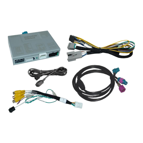
- Page 1 Video inserter RL3-MIB-TT Compatible with Audi vehicles with MMI Navigation Plus - MIB II infotainment with monitor in instrument Lamborghini vehicles with MIB infotainment with monitor in instrument Video-inserter for one rear-view camera and two more video inputs Product features ...
-
Page 2: Table Of Contents
Case 2Interface does not receive the reverse gear signal 2.6.2.3. Rear-view camera – presentation in instrument 2.7. Connecting video-interface and external keypad 2.8. Picture settings 3. Interface operation by external keypad 4. Specifications 5. FAQ – Trouble Shooting-Interface functions 6. Technical support Version 09.08.2021 HW: GD(V97)/(V33) RL3-MIB-TT... -
Page 3: Prior To Installation
Due to changes in the production of the vehicle manufacturer there’s always a possibility of incompatibility. 1.1. Delivery contents Take down the serial number of the interface and store this manual for support purposes: ____________________ Version 09.08.2021 HW: GD(V97)/(V33) RL3-MIB-TT... -
Page 4: Checking The Compatibility Of Vehicle And Accessories
Further it reads the vehicle’s digital signals out of the vehicle’s CAN-bus and converts them for the video interface. Version 09.08.2021 HW: GD(V97)/(V33) RL3-MIB-TT... -
Page 5: Settings Of The 8 Dip Switches (Black)
If set to OFF, the interface switches to factory picture while the reverse gear is engaged to display factory rear-view camera or factory optical park system picture. If set to ON, the interface switches to its rear-view camera input while the reverse gear is engaged. Version 09.08.2021 HW: GD(V97)/(V33) RL3-MIB-TT... -
Page 6: Monitor Selection (Dip 6, 7,-8)
The interface needs a permanent 12V source! 2.1. Place of installation The interface has to be installed at a suitable location behind the Radio or behind the glove compartment, depending on the place where the vehicle’s head unit is installed. Version 09.08.2021 HW: GD(V97)/(V33) RL3-MIB-TT... -
Page 7: Connection Schema
2.2. Connection schema Version 09.08.2021 HW: GD(V97)/(V33) RL3-MIB-TT... -
Page 8: Connection To The Factory Head Unit
12pin connector of the PNP harness. Clip in the female 12pin connector of the PNP harness in the previously become free position of the female Quadlock connector before finishing the Quadlock reconnection at the rear of the head-unit. Version 09.08.2021 HW: GD(V97)/(V33) RL3-MIB-TT... -
Page 9: Power - And Can Connection For The Video Interface
Connect the single, yellow wire of the 10pin power/CAN cable to +12V permanent and stabile power supply. Connect the single, black wire of the 10pin power/CAN cable to the vehicle’s negative ground. Version 09.08.2021 HW: GD(V97)/(V33) RL3-MIB-TT... -
Page 10: Analog Power Supply For The Video Interface
ACC-out (max 3A) and the purple coloured wire Manual ACC of the 12pin interface cable both have to be connected additionately to S-contact terminal 86s +12V (e.g. glove compartment illumination). Version 09.08.2021 HW: GD(V97)/(V33) RL3-MIB-TT... -
Page 11: Connection Of Video-Sources
12pin interface cable. Connect the video RCA of the Rear-view camera to the female RCA connector “Camera IN” of the 20pin interface cable (refer also to chapter “Video signal connection of the rear-view camera”) Version 09.08.2021 HW: GD(V97)/(V33) RL3-MIB-TT... -
Page 12: Audio Insertion
“Camera IN” while the reverse gear is engaged. Additionally, the +12V (max. 3A) power supply for the rear-view camera can be taken from the green wire of the 12pin interface cable. Version 09.08.2021 HW: GD(V97)/(V33) RL3-MIB-TT... - Page 13 Connect the output connector (87) of the relay to the rear-view camera’s power- cable, like you did it to the green “Reverse-IN” cable before. Connect stabile and permanent +12V to the relay’s input connector (30). Version 09.08.2021 HW: GD(V97)/(V33) RL3-MIB-TT...
-
Page 14: Rear-View Camera - Presentation In Instrument
2.6.2.3. Rear-view camera – presentation in instrument 2.7. Connecting video-interface and keypad Connect the female 4pin connector of the keypad to the male 4pin connector of the 12pin interface cable. Version 09.08.2021 HW: GD(V97)/(V33) RL3-MIB-TT... -
Page 15: Picture Settings
The following settings are available: Contrast Brightness Saturation Position H (horizontal) Position V (vertical) IR-AV1/2 (no function) – set to “none” Guide L/R (no function) UI-CNTRL (guide lines ON/OFF) – set to “OFF” Size H/V (picture size horizontal/vertical) Version 09.08.2021 HW: GD(V97)/(V33) RL3-MIB-TT... -
Page 16: Interface Operation By External Keypad
7V - 25V Stand-by power drain 12mA Power 210mA @12V Video input 0.7V - 1V Video input formats NTSC Temperature range -40°C to +85°C Dimensions video-box 119 x 24 x 114 mm (W x H x D) Version 09.08.2021 HW: GD(V97)/(V33) RL3-MIB-TT... -
Page 17: Faq - Trouble Shooting-Interface Functions
Camera input picture fluorescent light which shines Test camera under natural light outside the garage. flickers. directly into the camera. Camera input picture is Protection sticker not Remove protection sticker from lens. bluish. removed from camera lens. Version 09.08.2021 HW: GD(V97)/(V33) RL3-MIB-TT... -
Page 18: Technical Support
6pin to 8pin cable and isolate both ends. Technical Support Please note that direct technical support is only available for products purchased directly from NavLinkz GmbH. For products bought from other sources, contact your vendor for technical support. NavLinkz GmbH...
Need help?
Do you have a question about the RL3-MIB-TT and is the answer not in the manual?
Questions and answers