Table of Contents
Advertisement
Quick Links
All manuals and user guides at all-guides.com
r.LiNK Video-inserter
RL5-MIB-STD2
Video-inserter with 1 video input and 1 rear-view camera input
Compatible with VW vehicles
with Composition Media or Discover Media system
Skoda vehicles with Amundsen or Bolero system
Seat vehicles with Media system plus
Product features
Video-inserter for factory-infotainment systems
1 CVBS video-input for after-market device (e.g. USB-Player, DVB-T2 tuner)
1 CVBS rear-view camera video-input
Automatic switching to rear-view camera input on engagement of the reverse gear
Video-in-motion (ONLY for connected video-sources)
Video-inputs NTSC and PAL compatible
Version 10.09.2019
HW (V31)
RL5-MIB-STD2
Advertisement
Table of Contents

Related Manuals for NavLinkz r.LiNK RL5-MIB-STD2


Summary of Contents for NavLinkz r.LiNK RL5-MIB-STD2
- Page 1 All manuals and user guides at all-guides.com r.LiNK Video-inserter RL5-MIB-STD2 Video-inserter with 1 video input and 1 rear-view camera input Compatible with VW vehicles with Composition Media or Discover Media system Skoda vehicles with Amundsen or Bolero system Seat vehicles with Media system plus Product features ...
-
Page 2: Table Of Contents
All manuals and user guides at all-guides.com Contents 1. Prior to installation 1.1. Delivery contents 1.2. Checking the Interface compatibility of vehicle and accessories 1.3. Connectors – Video interface (daughter PCB) 2. Installation 2.1. Place of installation 2.2. Connection scheme 2.3. -
Page 3: Prior To Installation
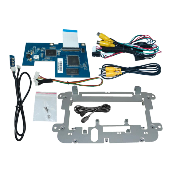
All manuals and user guides at all-guides.com 1. Prior to installation Read the manual prior to installation. Technical knowledge is necessary for installation. The place of installation must be free of moisture and away from heat sources. 1.1. Delivery contents Version 10.09.2019 HW (V31) RL5-MIB-STD2... - Page 4 All manuals and user guides at all-guides.com 1.2. Checking the compatibility of vehicle and accessories Compatibility vehicle Compatible vehicles Infotainment systems Amarok since model year 2017 Beetle (5C) since model year 2015 MIB STD2 PQ /+NAV Caddy (2K) since model year 2016 Composition Media / Discover Media Multivan (T6) since model year 2015 1x SD vertical left or 2x SD vertical left +...
-
Page 5: Connectors - Video Interface (Daughter Pcb)
All manuals and user guides at all-guides.com 1.3. Connectors - Video-interface (daughter PCB) The video-interface (daughter PCBs) converts the video signals of connected after-market sources in a factory monitor compatible picture signal which is inserted in the factory monitor, by using separate trigger options. 2. -
Page 6: Connection Scheme
All manuals and user guides at all-guides.com 2.2. Connection Scheme Version 10.09.2019 HW (V31) RL5-MIB-STD2... -
Page 7: Installation - Ribbon Cables Into The Monitor Panel
All manuals and user guides at all-guides.com 2.3. Installation - ribbon cables into the monitor panel Remove the head-unit, disconnect and remove the DVD drive unit and further disconnect and remove the frontpanel, which is fixed to the head-unit housing by 6 Torx screws (T9). Replace the original front panel-retaining plate, which is fixed by 9 Torx screws, against the enclosed exchange metal frame. -
Page 8: Warning Notes, Concerning The Installation Of Ribbon Cables
All manuals and user guides at all-guides.com After the ribbon cable connection, fix the daughtger PCB at the front panel-retaining plate by using the enclosed screws. After the daughter PCB’s previously mounted 20pin LVDS cable is lead out from the housing at a suitable location, reconnect the front panel with its 6 screws to the head unit’s housing. -
Page 9: Cable Connection - Daughter Pcb
All manuals and user guides at all-guides.com 2.4. Cable connection – daughter PCB Connect the 8pin interface cable’s 8pin connector and the menu pushbutton cable’s 4pin connector to the 6pin and 4pin connectors of the daughter PCB. Connect the 6pin interface cable’s single red colored wire to +12V terminal 30 (e.g. -
Page 10: After-Market Rear-View Camera
All manuals and user guides at all-guides.com 2.5. After-market rear-view camera: To switch the interface’s rear-view camera input, an external switching signal from the reverse gear light is required. As the reverse gear light signal contains electronic interference, a traditional open relay (e.g AC-RW-1230 with wiring AC-RS5) or filter (e.g. AC- PNF-RVC) is required. -
Page 11: Connection - Video Inputs
All manuals and user guides at all-guides.com 2.6. Connection – video inputs It is possible to connect one after-market video sources and one after-market rear-view camera to the video-interface. Before final installation of the peripheral devices, we recommend a test-run to detect a incompatibility of vehicle and interface. -
Page 12: Connection - Keypad
All manuals and user guides at all-guides.com 2.7. Connection – external keypad Connect the keypad’s female 4pin connector to the male 4pin connector of the 6pin interface cable. Version 10.09.2019 HW (V31) RL5-MIB-STD2... -
Page 13: Interface Operation By External Keypad
All manuals and user guides at all-guides.com 3. Interface operation by external keypad Use the external keypad to switch to the connected video source. Each press will switch between the factory video and the connected video source. 4. Picture settings The picture settings are adjustable by the 3 push-buttons of the daughjter PCB’s menu keypad. -
Page 14: Specifications
All manuals and user guides at all-guides.com 5. Specifications BATT/ACC range 7V - 25V Stand-by power drain Power 100mA @12V Video input 0.7V - 1V Video input formats NTSC / PAL RGB-video amplitude 0.7V with 75 Ohm impedance Temperature range -40°C to +85°C Dimensions PCB1 123x 11 x 76 mm (W x H x D) - Page 15 All manuals and user guides at all-guides.com FAQ – Trouble shooting Interface functions For any troubles which may occur, check the following table for a solution before requesting support from your vendor. Symptom Reason Possible solution Not all connectors have been reconnected to factory head- Connect missing connectors.
-
Page 16: Technical Support
All manuals and user guides at all-guides.com Technical Support Please note that direct technical support is only available for products purchased directly from NavLinkz GmbH. For products bought from other sources, contact your vendor for technical support. NavLinkz GmbH distribution/tech dealer-support...
Need help?
Do you have a question about the r.LiNK RL5-MIB-STD2 and is the answer not in the manual?
Questions and answers