Advertisement
Quick Links
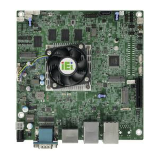
Mini-ITX SBC Supports Intel® Celeron® J6412 on-board SoC with
HDMI, DP, iDPM, 2.5GbE LAN, M.2, PCIe x4 Slot, SATA 6Gb/s,
COM, USB 3.2 Gen 2, iAUDIO, 0°C~60°C and RoHS
Quick Installation Guide
Package List
KINO-EHL-J6412 package includes the following items:
1 x KINO-EHL-J6412 single board computer
1 x SATA cable
1 x I/O shielding
1 x QIG
KINO-EHL-J6412
Version 1.0
June 9, 2022
©2022 Copyright by IEI Integration Corp.
All rights reserved.
Advertisement

Related Manuals for IEI Technology KINO-EHL-J6412


Summary of Contents for IEI Technology KINO-EHL-J6412
- Page 1 COM, USB 3.2 Gen 2, iAUDIO, 0°C~60°C and RoHS KINO-EHL-J6412 Quick Installation Guide Version 1.0 June 9, 2022 Package List KINO-EHL-J6412 package includes the following items: 1 x KINO-EHL-J6412 single board computer 1 x SATA cable 1 x I/O shielding ...
-
Page 2: Specifications
Specifications CPU: Intel® Celeron® J6412 on-board SoC (up to 2.6GHz, quad-core, 1.5M cache, TDP=10W) Memory: On-board 8GB 3200 MHz LPDDR4X (system max. 16GB) BIOS: AMI UEFI BIOS Dual BIOS for boot & recovery Graphics Engine: Intel® Gen11LP Gfx firmware and driver, Media SDK, OpenCL* 1.2, OpenGL 4.5, OpenGL-ES 3.2, Vulkan v1.1, DirectX ... - Page 3 Audio: 1 x iAUDIO (2x5 pin), supporting IEI AC-KIT-888S kit Front Panel: 1 x Front panel (2x7 pin, p=2.54; power LED, HDD LED, power button, reset button) Expansions: 1 x M.2 2230 A key (PCIe x1 / USB 2.0 signal) 1 x M.2 3052/3042/2242/2280 B key with SIM slot (PCIe x2 / USB 2.0 signal) 1 x PCIe x4, open-ended (PCIe Gen3 x1 signal)
-
Page 4: Ordering Information
All the drivers and utility for the https://download.ieiworld.com KINO-EHL-J6412 are available on IEI Resource Download Center. Type KINO-EHL-J6412 and press Enter to find all the relevant software, utilities, and documentation. To install software from the downloaded ISO file, mount the file... -
Page 5: Jumpers Setting And Connectors
Jumpers Setting and Connectors LABEL FUNCTION J_CMOS2 Clear CMOS button J_ATX_AT1 AT/ATX power mode setting switch J_BIOS1_1 BIOS1/BIOS2 select jumper J_DNX1 DNX mode setting jumper J_FLASH1 Flash descriptor override setting jumper IAUDIO1 Audio connector for IEI AC-KIT-888S kit ATX 12V power connector BAT1 Battery connector Buzzer connector... - Page 6 JUSB3, JUSB4 Internal USB 2.0 connectors M2_A_KEY M.2 A-key slot M2_B_KEY M.2 B-key slot PCIEX4_1 PCIe x4 slot (x1 signal) SIM slot (solder side) IDPM1 IEI iDPM slot External 12V DC input jack External 2.5GbE and USB 3.2 Gen 2 combo J_LAN1_USB1 connector J_LAN2_USB2...
- Page 7 J_DNX1: DNX Mode Setting Jumper PIN NO. DESCRIPTION Open Normal (default) Short Enable DNX Boot J_FLASH1: Flash Descriptor Override Setting Jumper PIN NO. DESCRIPTION Short 1 - 2 Disable (default) Short 2 - 3 Enable IAUDIO : Audio Connector for IEI AC-KIT-888S Kit PIN NO.
- Page 8 DIO1: Digital Input/Output Connector PIN NO. DESCRIPTION PIN NO. DESCRIPTION DOUT5 DOUT4 DOUT3 DOUT2 DOUT1 DOUT0 DIN5 DIN4 DIN3 DIN2 DIN1 DIN0 CPU_FAN1: Fan Connector PIN NO. DESCRIPTION PIN NO. DESCRIPTION FANIO +12V SYS_FAN2: Fan Connector PIN NO. DESCRIPTION PIN NO. DESCRIPTION FANIO F_PANEL1: Front Panel Connector...
- Page 9 COM3, COM4, COM5, COM6: RS-422/485 Serial Port Connectors PIN NO. DESCRIPTION PIN NO. DESCRIPTION S_ATA1: SATA 6Gb/s Connector PIN NO. DESCRIPTION PIN NO. DESCRIPTION SATA_RX‐ SATA_TX+ SATA RX+ SATA_TX‐ SATA_PWR1: SATA Power Connector PIN NO. DESCRIPTION PIN NO. DESCRIPTION I2C1: I C Connector PIN NO.
- Page 10 JEC2: Flash EC ROM Connector PIN NO. DESCRIPTION PIN NO. DESCRIPTION SPI_CS# +3.3V SPI_SO EC_DET_FLASH SPI_CLK SPI_SI J_CONSOLE1: BIOS Debug Connector PIN NO. DESCRIPTION PIN NO. DESCRIPTION +3.3V PSE_UART4_CTS PSE_UART4_TX PSE_UART4_RTS PSE_UART4_RX DEBUG_SPI1: EC Debug Connector PIN NO. DESCRIPTION PIN NO. DESCRIPTION EDICLK EDICS...
- Page 11 JUSB3, JUSB4: Internal USB 2.0 Connectors PIN NO. DESCRIPTION PIN NO. DESCRIPTION USB_DATA- USB_DATA+ USB_DATA+ USB_DATA- M2_A_KEY: M.2 A-key Slot PIN NO. DESCRIPTION PIN NO. DESCRIPTION +V3.3A USB+ +V3.3A USB- Module Key Module Key Module Key Module Key Module Key Module Key Module Key Module Key...
- Page 12 WLAN_PERST# +V3.3A_WLAN +V3.3A_WLAN +V3.3A_WLAN PEWAKE# +V3.3A +V3.3A M2_B_KEY: M.2 B-key Slot PIN NO. DESCRIPTION PIN NO. DESCRIPTION WWAN_CONFIG3 +3.3V_WWAN +3.3V_WWAN WWAN_FCP_OFF USB_D+ WWAN_DISABLE USB_D- Module Key Module Key Module Key Module Key Module Key Module Key Module Key PSE_I2S1_SCLK Module Key WWAN_CONFIG0 PSE_I2S1_TXD PCIE_WAKE#...
- Page 13 PCIE_TXP7 SSD_DEVSLP PCIE_RXN6 PCIE_RXP6 PCIE_TXN6 PCIE_TXP6 WWAN_PERST# CLK_M2_B_N WWAN_WAKE# CLK_M2_B_P WWAN_SIM1_DET WWAN_RST WWAN_SUSCLK DET_OS-PCIE/ +3.3V GND-SATA +3.3V +3.3V WWAN_CONFIG2 CN4: SIM Card Slot (on solder side) PIN NO. DESCRIPTION PIN NO. DESCRIPTION SIM_VCC SIM_RST SIM_CLOCK SIM_DATA...
- Page 14 J_LAN1_USB1 External USB 3.2 Gen 2 Connectors PIN NO. DESCRIPTION PIN NO. DESCRIPTION USB_DATA- USB_DATA- USB_DATA+ USB_ DATA+ USB3_RX- USB3_RX- USB3_RX+ USB3_ RX+ USB3_TX- USB3_TX- USB3_TX+ USB3_TX+ 2.5GbE RJ-45 Connector PIN NO. DESCRIPTION PIN NO. DESCRIPTION LAN1_MDI0P LAN1_MDI2P LAN1_MDI0N LAN1_MDI2N LAN1_MDI1P LAN1_MDI3P LAN1_MDI1N...
- Page 15 COM1: External Dual RS-232 Connector PIN NO. DESCRIPTION PIN NO. DESCRIPTION DCD1 DCD2 RXD1 RXD2 TXD1 TXD2 DTR1 DTR2 GND1 GND2 DSR1 DSR2 RTS1 RTS2 CTS1 CTS2 CN2: External 12V DC Input Jack PIN NO. DESCRIPTION PIN NO. DESCRIPTION +12V...
- Page 16 HDMI_DP1 External DP Connector PIN NO. DESCRIPTION PIN NO. DESCRIPTION DATA_0P DATA_3N DATA_0N CONFIG1 DATA_1P CONFIG2 AUX_P DATA_1N DATA_2P AUX_N DP HPD DATA_2N DATA_3P DP PWR External HDMI Connector PIN NO. DESCRIPTION PIN NO. DESCRIPTION HDMI2_DATA2 HDMI2_DATA2# HDMI2_DATA1 HDMI2_DATA1# HDMI2_DATA0 HDMI2_DATA0# HDMI2_CLK HDMI2_CLK#...
- Page 17 Board Layout: Jumper and Connector Locations (Unit: mm)
Need help?
Do you have a question about the KINO-EHL-J6412 and is the answer not in the manual?
Questions and answers