Sign In
Upload
Manuals
Brands
IEI Technology Manuals
Single board computers
KINO-CV-N26001-R10
IEI Technology KINO-CV-N26001-R10 Manuals
Manuals and User Guides for IEI Technology KINO-CV-N26001-R10. We have
1
IEI Technology KINO-CV-N26001-R10 manual available for free PDF download: User Manual
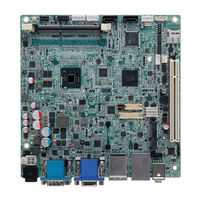
IEI Technology KINO-CV-N26001-R10 User Manual (120 pages)
Industrial Mini ITX
Brand:
IEI Technology
| Category:
Single board computers
| Size: 6.61 MB
Table of Contents
Table of Contents
4
Introduction
13
Introduction
14
Figure 1-1: KINO-CV-D25501/N26001
14
Benefits
15
Features
15
Connectors
16
Figure 1-2: Connectors
16
Dimensions
17
Figure 1-3: Dimensions (MM)
17
Data Flow
18
Figure 1-4: Data Flow Diagram
18
Technical Specifications
19
Table 1-1: Technical Specifications
21
Packing List
22
Anti-Static Precautions
23
Unpacking Precautions
23
Packing List
24
Optional Items
25
Table 2-1: Packing List
25
Table 2-2: Optional Items
25
Connector Pinouts
26
Peripheral Interface Connectors
27
Layout
27
Figure 3-1: Connector and Jumper Locations
27
Peripheral Interface Connectors
28
External Interface Panel Connectors
29
Internal Peripheral Connectors
29
Table 3-1: Peripheral Interface Connectors
29
Table 3-2: Rear Panel Connectors
29
Battery Connector
30
Figure 3-2: Battery Connector Location
30
Table 3-3: Battery Connector Pinouts
30
Digital I/O Connector
31
Figure 3-3: Digital I/O Connector Location
31
Table 3-4: Digital I/O Connector Pinouts
31
Fan Connectors
32
Front Audio Connector
32
Figure 3-4: Fan Connector Locations
32
Table 3-5: Fan Connector Pinouts
32
Front Panel Connector
33
Figure 3-5: Front Audio Connector Location
33
Table 3-6: Front Audio Connector Pinouts
33
Keyboard/Mouse Connector
34
Figure 3-6: Front Panel Connector Location
34
Table 3-7: Front Panel Connector Pinouts
34
LVDS Connector (LVDS1)
35
Figure 3-7: Keyboard/Mouse Connector Location
35
Table 3-8: Keyboard/Mouse Connector Pinouts
35
LVDS Connector (LVDS2)
36
Figure 3-8: LVDS1 Connector Location
36
Table 3-9: LVDS1 Connector Pinouts
36
Figure 3-9: LVDS2 Connector Location
37
Table 3-10: LVDS2 Connector Pinouts
37
LVDS Backlight Connectors
38
Microsd Card Slot
38
Figure 3-10: LVDS Backlight Inverter Connectors
38
Table 3-11: Backlight Inverter Connector Pinouts
38
Pcie Mini Card Slot
39
Figure 3-11: Microsd Slot Location
39
Table 3-12: Microsd Slot Connector Pinouts
39
Figure 3-12: Pcie Mini Card Slot Location
40
Power Connector (9 V-28 V)
41
Table 3-13: Pcie Mini Card Slot Pinouts
41
Power Button
42
Figure 3-13: ATX Power Connector Location
42
Figure 3-14: Power Button Location
42
Table 3-14: Power Connector Pinouts
42
Serial Port Connectors (COM3, COM5, COM6)
43
Figure 3-15: RS-232 Serial Port Connector Location
43
Table 3-15: Serial Port Connector Pinouts
43
RS-422/485 Serial Port Connector (COM4)
44
Figure 3-16: RS-422/485 Serial Port Connector Location
44
Table 3-16: RS-422/485 Serial Port Connector Pinouts
44
SATA Drive Connectors
45
Table 3-17: D-Sub 9 RS-422/485 Pinouts
45
SATA Power Connectors
46
Figure 3-17: SATA Drive Connector Location
46
Table 3-18: SATA Drive Connector Pinouts
46
SO-DIMM Connector
47
Figure 3-18: SATA Power Connector Locations
47
Table 3-19: SATA Power Connector Pinouts
47
SPDIF Connector
48
Figure 3-19: SO-DIMM Connector Location
48
Figure 3-20: SPDIF Connector Location
48
SPI Flash Connector
49
Figure 3-21: SPI Flash Connector Location
49
Table 3-20: SPDIF Connector Pinouts
49
Table 3-21: SPI Flash Connector Pinouts
49
USB 2.0 Connectors
50
Figure 3-22: USB Connector Locations
50
Table 3-22: USB Port Connector Pinouts
50
External Interface Connectors
51
Audio Connector
51
Figure 3-23: External Interface Connectors
51
Ethernet and USB 2.0 Combo Connector
52
Figure 3-24: Audio Connector
52
Figure 3-25: Ethernet Connector
52
Table 3-23: LAN Pinouts
52
Ethernet and USB 3.0 Combo Connector
53
Table 3-24: Connector Leds
53
Table 3-25: USB Port Pinouts
53
HDMI Connector
54
Figure 3-25: Ethernet Connector
54
Power Connector (9 V-28 V, Power Adapter)
55
Figure 3-26: HDMI Connector
55
Table 3-26: HDMI Connector Pinouts
55
Serial Port Connectors (COM1, COM2)
56
Figure 3-27: 4-Pin Power DIN Connection
56
Figure 3-28: Serial Port Pinout Locations
56
Table 3-27: Serial Port Pinouts
56
VGA Connector
57
Figure 3-29: VGA Connector
57
Table 3-28: VGA Connector Pinouts
57
Installation
58
Anti-Static Precautions
59
Installation Considerations
60
So-DIMM Installation
61
Figure 4-1: SO-DIMM Installation
61
Pcie Mini Card Installation
62
Figure 4-2: Pcie Mini Card Installation
62
Jumper Settings
63
AT/ATX Mode Selection
63
Table 4-1: Jumpers
63
Clear CMOS Jumper
64
Figure 4-3: AT/ATX Mode Selection Jumper Location
64
Table 4-2: AT/ATX Mode Selection
64
LVDS1 Voltage Selection
65
Figure 4-4: Clear CMOS Jumper Location
65
Table 4-3: Clear CMOS Jumper Settings
65
LVDS2 Voltage Selection
66
Figure 4-5: LVDS1 Voltage Selection Jumper Location
66
Table 4-4: LVDS1 Voltage Selection
66
Table 4-5: LVDS2 Voltage Selection
66
LVDS2 Resolution Selection
67
Figure 4-6: LVDS2 Voltage Selection Jumper Location
67
Pcie Mini/Msata Mode Selection
68
Figure 4-7: LVDS2 Resolution Selection Jumper Location
68
Table 4-6: LVDS2 Resolution Selection
68
Table 4-7: Pcie Mini/Msata Mode Selection
68
Chassis Installation
69
Airflow
69
Motherboard Installation
69
Figure 4-8: Pcie Mini/Msata Mode Selection Jumper Location
69
Internal Peripheral Device Connections
70
SATA Drive Connection
70
Figure 4-9: SATA Drive Cable Connection
70
USB Cable Connection
71
Figure 4-10: Dual USB Cable Connection
71
Keyboard/Mouse Connector (Optional)
72
Figure 4-11: Keyboard/Mouse Y-Cable Connection
72
Software Installation
73
Figure 4-18: Introduction Screen
74
Figure 4-19: Available Drivers
74
Bios
76
Introduction
77
Starting Setup
77
Using Setup
77
Getting Help
78
Unable to Reboot after Configuration Changes
78
BIOS Menu Bar
78
Table 5-1: BIOS Navigation Keys
78
Main
79
Advanced
80
ACPI Configuration
81
RTC Wake Settings
82
CPU Configuration
83
IDE Configuration
85
USB Configuration
86
F81866 Super IO Configuration
87
Serial Port N Configuration
88
F81866 H/W Monitor
94
Smart Fan Mode Configuration
95
Serial Port Console Redirection
96
IEI Feature
97
Chipset
98
Host Bridge
99
Intel IGD Configuration
100
South Bridge
101
Boot
103
Security
105
Exit
105
ABIOS Options
107
B Terminology
110
C Digital I/O Interface
114
Introduction
115
Assembly Language Sample
116
Assembly Language Sample 2
116
D Hazardous Materials Disclosure
117
Hazardous Materials Disclosure Table for IPB Products Certified as Rohs Compliant under 2002/95/EC Without Mercury
118
Advertisement
Advertisement
Related Products
IEI Technology KINO-CV-N26001
IEI Technology KINO-CV-D25501-R10
IEI Technology KINO-DAL-N2
IEI Technology KINO-DBT-N29301-R10
IEI Technology KINO-DBT-N28071-R10
IEI Technology KINO-DQM871-i1
IEI Technology KINO-PVN-D5251-R10
IEI Technology KINO-PV-D5253-D4253
IEI Technology KINO-TGL-U
IEI Technology KINO-TGL-U-i3-R10
IEI Technology Categories
Motherboard
Touch Panel
Computer Hardware
Single board computers
Desktop
More IEI Technology Manuals
Login
Sign In
OR
Sign in with Facebook
Sign in with Google
Upload manual
Upload from disk
Upload from URL