Table of Contents
Advertisement
S
®
LEVIFLOW
Single-Use Sensors:
®
LEVIFLOW
Converter:
This manual contains information necessary for the safe and proper use of the LEVIFLOW
flowmeter series. Included are specifications for the standard configuration, components, and instructions regarding its
use, installation, operation, adjustment, inspection and maintenance. For special configuration of the LEVIFLOW
flowmeters refer to accompanying information. If the flowmeters shall be configured for other parameter settings, then
®
the Levitronix
Service Software (see relevant manual Levitronix
channel converter LFC-6CIO-PC the Levitronix
familiarize yourself with the contents of this manual to ensure the safe and effective use of this product. After reading,
please store the manual where the personnel responsible for operating can readily refer to it at any time.
PL-4509-00, Rev09, DCO# 21-230
LEVIFLOW
-U
INGLE
SE
U
SER
®
Service Software version V2.0.5.0 or higher is needed. Please
User Manual for LEVIFLOW
®
LFS-SU
F
LOWMETERS
M
ANUAL
LFS-03SU, -06SU, -10SU, -15SU, -20SU
LFC-1C-PC, LFC-6CIO-PC (6-Channel)
Doc.# PL-4048-00) is necessary. For the multi-
®
LFS-SU Flowmeters
www.levitronix.com
®
LFS-SU single-use
®
First Release: 11-Dec-2014
Last Update: 07-Oct-2021
Advertisement
Table of Contents

Related Manuals for Levitronix LEVIFLOW LFS-SU


Summary of Contents for Levitronix LEVIFLOW LFS-SU
- Page 1 If the flowmeters shall be configured for other parameter settings, then ® the Levitronix Service Software (see relevant manual Levitronix Doc.# PL-4048-00) is necessary. For the multi- ® channel converter LFC-6CIO-PC the Levitronix Service Software version V2.0.5.0 or higher is needed. Please familiarize yourself with the contents of this manual to ensure the safe and effective use of this product.
-
Page 2: Table Of Contents
4.2.2 Display Messages ................................22 4.2.3 Operation with PLC Interface............................23 ® 4.2.4 Operation with Levitronix Service Software ........................24 4.2.5 Operation with RS485 ..............................24 System Operation with LFC-6CIO-PC ......................25 4.3.1 Standard Operation with PLC Interface .......................... 25 4.3.2... -
Page 3: Safety Precautions
1 Safety Precautions CAUTION Do not under any circumstances open the converter or sensor housing. Levitronix does not assume responsibility for any damage, which occurs under such circumstances. WARNING Hazardous voltage may be present. In case of the usage of an inadequate AC/DC power supply, mains voltages may be present (even if the system is designed for 24VDC). -
Page 4: Specifications
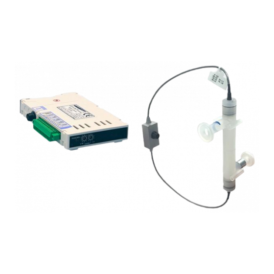
® User Manual for LEVIFLOW LFS-SU Flowmeters www.levitronix.com 2 Specifications 2.1 Component Overview ® Figure 1: LEVIFLOW flow sensors and converter Figure 2: Accessories Flow In Single-Channel Converter LFC-1C-PC Digital Signal Processor ® LEVIFLOW ® LEVIFLOW Flow Sensors Starter-Kit USB Stick... - Page 5 ® User Manual for LEVIFLOW LFS-SU Flowmeters www.levitronix.com 1% Accuracy Pos. Part Name Article # Fitting Connector Note Flow Range 35 – 800 ml/min LFS-03SU-Z 100-30375 LFS-03SU-Z-G25 100-30399 6 – 800 ml/min LFS-03SU-Z-SC1 100-30418 LFS-03SU-Z-SC1-G25 100-30419 Triclamp 3/8” 1.7 – 8 l/min...
-
Page 6: Standard System Configurations
® User Manual for LEVIFLOW LFS-SU Flowmeters www.levitronix.com 2.2 Standard System Configurations 2.2.1 Single Channel System Configuration with LFC-1C-PC Single-Channel Converter LFC-1C-PC Flow Out Digital Signal Processor Piezo Transducers In-/Output Electrical Interface Flow In Power Supply: 24 VDC EMI Ferrite... -
Page 7: Specifications Of Converter
10 sec. Warm-Up Time for Full Performance Measurements 30 min. Table 4: Specifications for converters LFC-1C-PC Note 1: Other parameters available and described in the Levitronix Service Software manual. 2.3.2 Specifications of Multi-Channel Converter LFC-6CIO-PC Characteristics 6-Channel Converter LFC-6CIO-PC Power Supply Voltage / Current / Inrush Current 24 VDC ±... -
Page 8: Overview Of Parameter Configuration
Table 6 shows the standard (“Default”) and possible parameter configurations of the flowmeters. This user ® manual is dealing with the standard configuration. For setting up other configurations the Levitronix Service Software is needed. Consult the “Service Software User Manual” (see reference on title page of this manual) for more detailed description. -
Page 9: Specifications Of Single-Use Sensors
® User Manual for LEVIFLOW LFS-SU Flowmeters www.levitronix.com 2.4 Specifications of Single-Use Sensors 2.4.1 General Specifications LFS-03SU LFS-06SU LFS-10SU LFS-15SU LFS-20SU Characteristics LFS-03SU-SC1 LFS-06SU-SC1 LFS-10SU-SC1 LFS-15SU-SC1 LFS-20SU-SC1 0 – 0.8 l/min 0 – 8 l/min 0 – 20 l/min 0 – 50 l/min 0 –... -
Page 10: Basic Dimensions Of Main Components
® User Manual for LEVIFLOW LFS-SU Flowmeters www.levitronix.com 2.5 Basic Dimensions of Main Components 2.5.1 Dimensions of Sensors Figure 7: Dimensions of LFS-03SU and LFS-06SU flow sensors Triclamp Dimensions in [mm] Sensor Fitting Size Type (ASME BPE 2009) Ø 12.7 (= 1/2”) LFS-10SU-Z 1/2"... -
Page 11: Dimensions Of Converters
® User Manual for LEVIFLOW LFS-SU Flowmeters www.levitronix.com 2.5.2 Dimensions of Converters 100-30374 LFC-1C-PC Figure 9: Dimensions and layout of interfaces of converter LFC-1C-PC Termination Box) Connector Box (RS485 and Supply Bus) EMI Ferrite Figure 10: Dimensions and stacking concept of multi-channel converter LFC-6CIO-PC... -
Page 12: Dimensions Of Adaptor Cables
® User Manual for LEVIFLOW LFS-SU Flowmeters www.levitronix.com 2.5.3 Dimensions of Adaptor Cables Length = 1,3,6 m Sealing Gasket Delivered with protective dust cap on connector) Mounting Panel Dimensions Converter Connector Mounting Wall Wall-mountable Adaptor Figure 11: Dimensions of wall mountable extension cable LFE-C.2 (Can be used for electrical cabinet mounting. -
Page 13: Installation
® User Manual for LEVIFLOW LFS-SU Flowmeters www.levitronix.com 3 Installation 3.1 Installation of Converter LFC-1C-PC 3.1.1 Overview and Preparation Interface Connector (12 Pin) LFC-1C-PC DIN Rail Mounting Sensor Connector Re-Zero Button LOW ADRS 4 Digit Display High ADRS Figure 13: Single channel converter LFC-1C-PC... -
Page 14: Instructions For Electrical Installation
Service Software can be used to debug and configure the flowmeter over the RS485. For communication with RS485 the MODBUS protocol can be requested at Levitronix 3.1.2 Instructions for Electrical Installation 1. Remove the DC power from the converter. -
Page 15: Instructions For Mechanical Installation
® User Manual for LEVIFLOW LFS-SU Flowmeters www.levitronix.com 3.1.3 Instructions for Mechanical Installation WARNING Hazardous voltage may be present. In order to avoiding fluid spills shorting voltages within the converter, place the controller in a spill protected environment (for example protected electronic cabinets). -
Page 16: Installation Of Converter Lfc-6Cio-Pc
® User Manual for LEVIFLOW LFS-SU Flowmeters www.levitronix.com 3.2 Installation of Converter LFC-6CIO-PC 3.2.1 Overview and Preparation Fixation Bars Connector (locked) Fixation Bars Digital I/O (un-locked) Sensor Connectors: Channel #6 Channel #1 Fixation Bars (locked on both sides) Connector Analog Output... - Page 17 “High ADRS” x 10 + “Low ADRS” x 1 ® The Levitronix Service Software can be used to debug and configure the flowmeter over the RS485. For communication with RS485 the MODBUS protocol can be requested at Levitronix PL-4509-00, Rev09, DCO# 21-230...
-
Page 18: Instructions For Electrical Installation
® User Manual for LEVIFLOW LFS-SU Flowmeters www.levitronix.com 3.2.2 Instructions for Electrical Installation 1. Remove the DC power supply from the converter. 2. Remove the interface connector on the connector box (see Figure 16). 3. Attach the necessary wires (AWG 14-26) according to the pin specifications in Table 9, Table 10 or Table 11. -
Page 19: Instructions For Mechanical Installation
® User Manual for LEVIFLOW LFS-SU Flowmeters www.levitronix.com 3.2.3 Instructions for Mechanical Installation WARNING Hazardous voltage may be present. In order to avoiding fluid spills shorting voltages within the converter, place it in a spill protected environment (for example protected electronic cabinets). -
Page 20: Installation Of Sensors
® User Manual for LEVIFLOW LFS-SU Flowmeters www.levitronix.com 3.3 Installation of Sensors 3.3.1 Overview and Preparation LFS-20SU 0 – 80 l/min LFS-15SU 0 – 50 l/min LFS-10SU 0 – 20 l/min LFS-06SU LFS-03SU 0 – 8 l/min 0 – 0.8 l/min... -
Page 21: Instructions For Mechanical And Hydraulic Installation
1. For mounting and exchanging the sensors and assure proper operation it is recommended to use the LMK-x.2 mounting ® brackets, which can be ordered according to Table 3 and are shown in Figure 2. Contact Levitronix for detailed drawing specifications. -
Page 22: Operation
® User Manual for LEVIFLOW LFS-SU Flowmeters www.levitronix.com 4 Operation 4.1 General Timing Specifications 4.1.1 Startup Time ® After power-on a LEVIFLOW converter startup sequence with information about converter type, firmware version and baud rate are proceeded. During this sequence flow measurement is not performed. Start-up time is about 8 seconds. -
Page 23: Operation With Plc Interface
Figure 21. This setup additionally shows how to connect a push-button to digital input (e.g. for reset of ® volume counter, which shall be configured with Levitronix Service Software). Figure 22 shows an example ® how to connect the PLC of the converter to a Levitronix pump system. Supply +24V Supply GND DC24V+... -
Page 24: Operation With Levitronix
LFS-SU Flowmeters www.levitronix.com ® 4.2.4 Operation with Levitronix Service Software ® For debugging, data collection and configuration of the flowmeter system the Levitronix Service Software is ® ® available at Levitronix . Contact Levitronix for a sample of the configuration software and the according manual (see reference on title page of this manual). -
Page 25: System Operation With Lfc-6Cio-Pc
6) or indicates, which flow is shown in display (when channel selection is set to 0). ® 4.3.4 Operation with Levitronix Service Software ® For debugging, data collection and configuration of the flowmeter system the Levitronix Service Software is ® ® available at Levitronix . -
Page 26: Inspection And Maintenance
6.2 Troubleshooting with Levitronix Service Software ® ® More detailed error analysis can be done with the Levitronix Service Software. Contact Levitronix for a sample of the configuration software and the according manual (see reference on title page of this manual). -
Page 27: Technical Support
® User Manual for LEVIFLOW LFS-SU Flowmeters www.levitronix.com 7 Technical Support For troubleshooting, support and detailed technical information contact Levitronix Technical Service Department: Levitronix Technical Service Department Technoparkstr. 1 CH-8005 Zurich Switzerland Phone for US: 888-569 07 18... -
Page 28: Appendix
® User Manual for LEVIFLOW LFS-SU Flowmeters www.levitronix.com 8 Appendix 8.1 Regulatory Status 8.1.1 CE Marking ® The LEVIFLOW flowmeters with single-use flow sensor, in its various configurations, is in conformity with the below mentioned European Directives. The flowmeter system is thought to be used in hydraulic circuits of production equipment of Bioprocessing and Pharmaceutical industry. -
Page 29: Symbols And Signal Words
® User Manual for LEVIFLOW LFS-SU Flowmeters www.levitronix.com 8.2 Symbols and Signal Words Symbol / Description Type Source Signal Word Indication of an imminently hazardous situation that, if DANGER not avoided, will result in death or severe injury. Signal word...
Need help?
Do you have a question about the LEVIFLOW LFS-SU and is the answer not in the manual?
Questions and answers