Table of Contents
Advertisement
LEVIFLOW
F
M
LOW
®
LEVIFLOW
Sensors:
®
LEVIFLOW
Converter: Single-Channel LFC-1C-PC
This manual contains information necessary for the safe and proper use of the LEVIFLOW
series. Included are specifications for the standard configuration, components, and instructions regarding its use,
installation, operation, adjustment, inspection and maintenance. For special configuration of the LEVIFLOW
flowmeters refer to accompanying information. If the flowmeters must be configured for other parameter settings, then
®
the Levitronix
Service Software (with according manual Levitronix
channel converter LFC-6CIO-PC the Levitronix
familiarize yourself with the contents of this manual to ensure the safe and effective use of this product. After reading,
please store the manual where the personnel responsible for operating can readily refer to it at any time.
PL-4507-00, Rev08, DCO# 20-024
ETERS FOR
U
M
SER
LFSC-05D (1 l/min), LFSC-08D (4 l/min)
LFSC-12D (20 l/min), LFSC-22D (80 l/min),
LFSC-30D (160 l/min)
Multi-Channel LFC-6CIO-PC
®
Service Software version V2.0.5.0 or higher is needed. Please
User Manual for LEVIFLOW
®
C
-O
LAMP
F
LEXIBLE
ANUAL
Doc.# PL-4048-00) is necessary. For the multi-
®
LFSC-D Flowmeters
www.levitronix.com
N
T
UBING
®
clamp-on flowmeter
First Release: 18-Dec-14
Last Update: 29-Jan-20
®
Advertisement
Table of Contents

Subscribe to Our Youtube Channel
Related Manuals for Levitronix LEVIFLOW LFSC-D Series


Summary of Contents for Levitronix LEVIFLOW LFSC-D Series
- Page 1 If the flowmeters must be configured for other parameter settings, then ® the Levitronix Service Software (with according manual Levitronix Doc.# PL-4048-00) is necessary. For the multi- ® channel converter LFC-6CIO-PC the Levitronix Service Software version V2.0.5.0 or higher is needed. Please familiarize yourself with the contents of this manual to ensure the safe and effective use of this product.
-
Page 2: Table Of Contents
Standalone Operation with Display ..........................23 4.2.2 Operation with PLC Interface............................24 ® 4.2.3 Operation with Levitronix Service Software ........................25 Operation with RS485 ............................25 System Operation with LFC-6CIO-PC ......................26 4.4.1 Standard Operation with PLC Interface .......................... 26 4.4.2... -
Page 3: Safety Precautions
1 Safety Precautions CAUTION Do not under any circumstances open the converter or sensor housing. Levitronix does not assume responsibility for any damage, which occurs under such circumstances. WARNING Hazardous voltage may be present. In case of the usage of an inadequate AC/DC power supply, mains voltages may be present (even if the system is designed for 24VDC). -
Page 4: Specifications
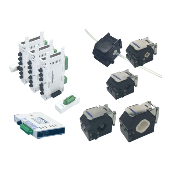
® User Manual for LEVIFLOW LFSC-D Flowmeters www.levitronix.com 2 Specifications 2.1 Component Overview ® Figure 1: LEVIFLOW flowmeter components Figure 2: Accessories Flow In Single-Channel Converter LFC-1C-PC Digital Signal Processor ® LEVIFLOW ® LEVIFLOW Starter-Kit USB Stick Life Science Flow Sensor... - Page 5 (C) with international AC mains inserts, sensor cable LFI-C.1-30 (D), LFC-1C-PC-SK 100-91072 Converter Starter Kit (A-H) converter connection cable LFI-D.1 (E), RS485/USB cable YN-485I-TR (F), USB stick with Levitronix Service Softw. and product Literature (G). ® Table 2: LEVIFLOW converters for clamp-on sensor Pos. Part Name...
-
Page 6: Standard System Configuration
® User Manual for LEVIFLOW LFSC-D Flowmeters www.levitronix.com 2.2 Standard System Configuration Flow In Single-Channel Converter LFC-1C-PC ® Digital LEVIFLOW Signal Processor Clamp-On Flowsensor LFSC-xxD Piezo Transducers Electrical Interface In-/Output Power Supply: 24 VDC EMI Ferrite Flow Out Analog and... -
Page 7: Specifications Of Flow Sensors
® User Manual for LEVIFLOW LFSC-D Flowmeters www.levitronix.com 2.3 Specifications of Flow Sensors Characteristics LFSC-05D LFSC-08D LFSC-12D LFSC-22D LFSC-30D 0 – 1 l/min 0 – 4 l/min 0 – 20 l/min 0 – 80 l/min 0 – 160 l/min Flow Range [l/min] Accuracy of Reading ±5 % for >... -
Page 8: Overview Of Parameter Configuration
® User Manual for LEVIFLOW LFSC-D Flowmeters www.levitronix.com 2.5 Overview of Parameter Configuration Table 8 shows the standard (“Default”) and possible parameter configurations of the clamp-on flowmeters. This user manual is dealing with the standard configuration. For setting up other configurations the ®... -
Page 9: Basic Dimensions Of Main Components
® User Manual for LEVIFLOW LFSC-D Flowmeters www.levitronix.com 2.6 Basic Dimensions of Main Components 2.6.1 Dimensions of Clamp-On Sensors Type 1 Type 2 Clamp Dimensions in [mm] Sensor Type Type LFSC-05D 67.2 44.5 M6 x 6 LFSC-08D 67.2 44.5 M6 x 6 LFSC-12D 67.2... -
Page 10: Dimensions Of Adaptor Cables
® User Manual for LEVIFLOW LFSC-D Flowmeters www.levitronix.com Termination Box) Connector Box (RS485 and Supply Bus) EMI Ferrite Figure 8: Dimensions and stacking concept of multi-channel converter LFC-6CIO-PC 2.6.3 Dimensions of Adaptor Cables Connector Hirose Plug Male Length = 3m... - Page 11 ® User Manual for LEVIFLOW LFSC-D Flowmeters www.levitronix.com Length = 1m Mounting Panel Dimensions Figure 10: Dimensions of wall mountable extension cable LFE-C.2 (Can be used for electrical cabinet mounting. Minimum bending radius > 10 x cable radius.) PL-4507-00, Rev08, DCO# 20-024...
-
Page 12: Installation
® User Manual for LEVIFLOW LFSC-D Flowmeters www.levitronix.com 3 Installation 3.1 Installation of Converter LFC-1C-PC 3.1.1 Overview and Preparation Interface Connector (12 Pin) LFC-1C-PC DIN Rail Mounting Sensor Connectors Re-Zero Button LOW ADRS 4 Digit Display High ADRS Figure 11: Single channel converter LFC-1C-PC... -
Page 13: Instructions For Electrical Installation
Service Software can be used to debug and configure the flowmeter over the RS485. For communication with RS485 the MODBUS protocol can be requested at Levitronix 3.1.2 Instructions for Electrical Installation 1. Remove the DC power from the converter. -
Page 14: Instructions For Mechanical Installation
® User Manual for LEVIFLOW LFSC-D Flowmeters www.levitronix.com 3.1.3 Instructions for Mechanical Installation WARNING Hazardous voltage may be present. In order to avoiding fluid spills shorting voltages within the converter, place the controller in a spill protected environment (for example protected electronic cabinets). -
Page 15: Installation Of Converter Lfc-6Cio-Pc
® User Manual for LEVIFLOW LFSC-D Flowmeters www.levitronix.com 3.2 Installation of Converter LFC-6CIO-PC 3.2.1 Overview and Preparation Fixation Bars Connector (locked) Fixation Bars Digital I/O (un-locked) Sensor Connectors: Channel #6 Channel #1 Fixation Bars (locked on both sides) Connector Analog Output... - Page 16 Figure 14 “High ADRS” x 10 + “Low ADRS” x 1 ® The Levitronix Service Software can be used to debug and configure the flowmeter over the RS485. For communication with RS485 the MODBUS protocol can be requested at ...
-
Page 17: Instructions For Electrical Installation
® User Manual for LEVIFLOW LFSC-D Flowmeters www.levitronix.com 3.2.2 Instructions for Electrical Installation 1. Remove the DC power supply from the converter. 2. Remove the interface connector on the connector box (see Figure 14). 3. Attach the necessary wires (AWG 14-26) according to the pin specifications in Table 10, Table 11 or Table 12. -
Page 18: Instructions For Mechanical Installation
® User Manual for LEVIFLOW LFSC-D Flowmeters www.levitronix.com 3.2.3 Instructions for Mechanical Installation WARNING Hazardous voltage may be present. In order to avoiding fluid spills shorting voltages within the converter, place it in a spill protected environment (for example protected electronic cabinets). -
Page 19: Installation Of Sensors
® User Manual for LEVIFLOW LFSC-D Flowmeters www.levitronix.com 3.3 Installation of Sensors 3.3.1 Overview and Preparation Flow Direction Transducer Area Flexible Tube Circular Connector (Watertight) Figure 17: Clamp-on flow sensor model LFSC-xxD 1. Every sensor comes delivered with a calibration sheet. Check if the S/N on the calibration sheet corresponds to the S/N on the type label of the sensor. -
Page 20: Mechanical And Hydraulic Installation
15. If Re-Zeroing is regularly necessary, automation is possible over the digital input of the converter. ® For the configuration of the digital input the Levitronix Service Software is needed. Consult the manual of the service software for more detailed description. -
Page 21: Instructions For Tube Mounting
® User Manual for LEVIFLOW LFSC-D Flowmeters www.levitronix.com 3.3.4 Instructions for Tube Mounting 1. Assure that the correct tubing type is used by CAUTION checking the according tubing information on the calibration sheet delivered with the clamp- Do not use aggressive cleaning agents, which could on sensor. - Page 22 ® User Manual for LEVIFLOW LFSC-D Flowmeters www.levitronix.com 6. Fit the clamp hinge into the according sensor 7. For a stable and repeatable measurement, it is body grove and close the clamp. very important that the tube is properly clamped into the square shape of the transducer area of the sensor.
-
Page 23: Operation
4.1.3 Zero Adjustment There are three possibilities to activate zero adjustment: ® Activating by Levitronix Service Software: Zero adjustment starts immediately after pressing corresponding button Activating by re-zero button on converter front (see Figure 11c): the reset button has to be pressed during 3 seconds to initiate zero adjustment. -
Page 24: Operation With Plc Interface
Figure 18: Controlling a shutoff valve by digital output of LFC-1C-PC converter Supply +24V Supply GND Levitronix Pump System Converter LFC-1C-PC Levitronix Pump System Converter LFC-1C ® Figure 19: Usage of PLC of LFC-1C-PC converter with a Levitronix pump system PL-4507-00, Rev08, DCO# 20-024... -
Page 25: Operation With Levitronix
® Figure 20: System operation with Levitronix Service Software 4.3 Operation with RS485 Operation from a mother system with communication over an RS485 bus is possible. The according MODBUS protocol can be requested at Levitronix PL-4507-00, Rev08, DCO# 20-024... -
Page 26: System Operation With Lfc-6Cio-Pc
6) or indicates, which flow is shown in display (when channel selection is set to 0). ® 4.4.4 Operation with Levitronix Service Software ® For debugging, data collection and configuration of the flowmeter system the Levitronix Service Software is ® ® available at Levitronix . -
Page 27: Inspection And Maintenance
- Use the standard EMI ferrites on the sensor cables. Table 14: Potential troubles and the possible countermeasures ® 6.2 Troubleshooting with Levitronix Service Software ® For debugging, data collection and configuration of the flowmeter system the Levitronix Service Software is ® ® available at Levitronix . Contact Levitronix for a sample of the service software and the according manual (see reference on title page of this manual). -
Page 28: Technical Support
® User Manual for LEVIFLOW LFSC-D Flowmeters www.levitronix.com 7 Technical Support For troubleshooting, support and detailed technical information contact Levitronix Technical Service Department: Levitronix Technical Service Department Technoparkstr. 1 CH-8005 Zurich Switzerland Phone for US: 888-569 07 18... -
Page 29: Appendix
® User Manual for LEVIFLOW LFSC-D Flowmeters www.levitronix.com 8 Appendix 8.1 Regulatory Status 8.1.1 CE Marking ® The LEVIFLOW clamp-on flowmeters of the LFSC-D series, in its various configurations, is in conformity with the below mentioned European Directives. The flowmeter system is thought to be used in hydraulic circuits of production equipment of Bioprocessing and Pharmaceutical industry. -
Page 30: Symbols And Signal Words
® User Manual for LEVIFLOW LFSC-D Flowmeters www.levitronix.com 8.2 Symbols and Signal Words Symbol / Description Type Source Signal Word Indication of an imminently hazardous situation that, if DANGER not avoided, will result in death or severe injury. Signal word...
Need help?
Do you have a question about the LEVIFLOW LFSC-D Series and is the answer not in the manual?
Questions and answers