Table of Contents
Advertisement
C
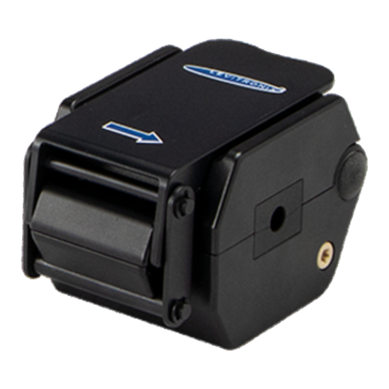
LFSC-iX Clamp-On Flowmeters
1/8x1/4", 1 l/min
LFSC-i06X:
1/2x3/4", 50 l/min
LFSC-i19X:
This manual contains information necessary for the safe and proper use of the LEVIFLOW
flowmeter series. Included are specifications for the standard configuration, components, and instructions regarding its
use, installation, operation, adjustment, inspection and maintenance. For special configuration of the LEVIFLOW
flowmeters refer to accompanying information. If the flowmeters shall be configured for other parameter settings, then
®
the Levitronix
Service Software (with manual Levitronix
necessary. Familiarize yourself with the contents of this manual to ensure the safe and effective use of this product.
After reading, please store the manual where the personnel responsible for operating can readily refer to it at any time.
PL-5001-00, Rev00, DCO# 21-084
LEVIFLOW
-O
LAMP
N
U
SER
LFSC-i10X:
LFSC-i25X:
User Manual for LEVIFLOW
®
F
M
LOW
ETERS
M
ANUAL
1/4x3/8", 4 l/min
3/4x1", 80 l/min
Doc.# PL-4048-00) with version V2.0.6.0 or higher is
®
LFSC-iX Flowmeters
www.levitronix.com
3/8x5/8", 20 l/min
LFSC-i16X:
", 160 l/min
LFSC-i35X:
1x1
3/8
®
LFSC-iX clamp-on
First Release: 27-Sep-2019
Last Update: 16-Apr-2021
®
Advertisement
Table of Contents

Related Manuals for Levitronix LEVIFLOW LFSC-i06X


Summary of Contents for Levitronix LEVIFLOW LFSC-i06X
- Page 1 ® the Levitronix Service Software (with manual Levitronix Doc.# PL-4048-00) with version V2.0.6.0 or higher is necessary. Familiarize yourself with the contents of this manual to ensure the safe and effective use of this product. After reading, please store the manual where the personnel responsible for operating can readily refer to it at any time.
-
Page 2: Table Of Contents
4.3.1 Operational Specifications .............................. 16 4.3.2 Typical Setups Using the PLC Interface ......................... 16 ® Operation with Levitronix Service Software....................16 Operation with RS485 ............................16 Measurement of Dynamic Flow Profiles ......................16 INSPECTION AND MAINTENANCE ........................16 TROUBLESHOOTING ............................. 17 Common Troubles ............................ -
Page 3: Safety Precautions
® User Manual for LEVIFLOW LFSC-iX Flowmeters www.levitronix.com 1 Safety Precautions CAUTION Do not under any circumstances open the flowmeter housing. ® Levitronix does not assume responsibility for any damage, which occurs under such circumstances. WARNING Hazardous voltage may be present. -
Page 4: Specifications
LFSC-i19X-001 100-30479 50 lpm temperature. ® ID = 3/4”=19.1 mm, OD = 1”=25.4 mm Other calibrations sets can be chosen with Levitronix Service LFSC-i25X-001 100-30480 80 lpm Software or with user panel LUI-B.1. ID = 1”= 25.4 mm, OD = 1 ”= 34.9 mm... -
Page 5: Standard System Configurations
Series Converter with Cable Splitting Cable Flow Out ® Figure 4: Configuration for PC with Levitronix Service Software (parameter configuration, Data logging and monitoring) (See section “Order Information” for details to numbered components and other options) Fieldbus PLC: (RS485 Modbus) -
Page 6: Specifications
® User Manual for LEVIFLOW LFSC-iX Flowmeters www.levitronix.com 2.3 Specifications Characteristics LFSC-i06X LFSC-i10X LFSC-i16X LFSC-i19X LFSC-i25X LFSC-i35X 0 – 1 l/min 0 – 4 l/min 0 – 20 l/min 0 – 50 l/min 0 – 80 l/min 0 – 160 l/min Flow Range [l/min] ±2 %... -
Page 7: Overview Of Parameter Configuration
2.4 Overview of Parameter Configuration Table 4 shows the standard (“Default”) and possible parameter configurations of the clamp-on flowmeters. ® This user manual is dealing with the standard configuration. For setting up other configurations the Levitronix Service Software is needed. Consult the Levtronix Service Software manual for more detailed description. -
Page 8: Installation
Please check the default factory setting on the article label. To switch to another calibration set the Levitronix® Service Software or the user panel LUI-B.1-02 can be used (see Section 4.2.2). -
Page 9: Overview Of Electrical Flowmeter Interface
® User Manual for LEVIFLOW LFSC-iX Flowmeters www.levitronix.com 3.2 Overview of Electrical Flowmeter Interface Pin 8 Digital Output 1 Pin 8 10 Ohm max. 24V DC / 100mA 5 ... 24V DC ital Output 2 Pin 9 Pin 9 10 Ohm max. - Page 10 ® User Manual for LEVIFLOW LFSC-iX Flowmeters www.levitronix.com Pin 8 Pin 8 Digital Output 1 max. 24V DC / 100mA 10 Ohm 5 ... 24V DC Pin 9 Pin 9 Digital Output 2 max. 24V DC / 100mA 10 Ohm 5 ...
-
Page 11: Instructions For Electrical Installation
Section 4.1.3 explains the zeroing possibilities. ® 10. The Levitronix Service Software can be used to debug and configure the flowmeter over the RS485. For communication with RS485 the MODBUS protocol can be requested at Levitronix PL-5001-00, Rev00, DCO# 21-084... -
Page 12: Mechanical And Hydraulic Installation
14. If Re-Zeroing is regularly necessary, automation is possible over the digital input of the flowmeter. ® For the configuration of the digital input the Levitronix Service Software is needed. Consult the manual of the service software for more detailed description. -
Page 13: Instructions For Tube Mounting
The LFSC-iX flowmeters are calibrated for multiple tubing types and liquid temperatures. Please check the default factory setting on the article label. To switch to another calibration set the Levitronix® Service Software or the user panel LUI-B.1-02 can be used (see user manual). CAUTION Do not use aggressive cleaning agents, which could attack the sensor surface and its parts. - Page 14 ® User Manual for LEVIFLOW LFSC-iX Flowmeters www.levitronix.com Do not squeeze the tube during the clamp-on procedure! 7. For a stable and repeatable measurement, it is 6. Fit the clamp hinge into the according sensor very important that the tube is properly clamped body grove and close the clamp.
-
Page 15: Operation
4.1.3 Zero Adjustment The duration to perform a zero adjustment is < 30 seconds. Following options are available for zeroing: ® Activating by Levitronix Service Software. Activating by the user panel in the system menu functions. Activation by digital input (default configuration). -
Page 16: Operation With Plc Interface
4.3 Operation with PLC Interface 4.3.1 Operational Specifications ® Table 5 specifies the electrical interface for OEM operation with a PLC. For other configurations the Levitronix Service Software shall be used. 4.3.2 Typical Setups Using the PLC Interface Figure 9 and Figure 10 illustrate typical electrical setups how to connect signals to the flowmeter. -
Page 17: Troubleshooting
Table 8: LED messages on flowmeter and the possible countermeasures ® 6.3 Troubleshooting with Levitronix Service Software ® For debugging, data collection and configuration of the flowmeter system the Levitronix Service Software is ® ® available at Levitronix . Contact Levitronix for a sample of the service software and the according manual. -
Page 18: Appendix
® User Manual for LEVIFLOW LFSC-iX Flowmeters www.levitronix.com 8 Appendix 8.1 Regulatory Status 8.1.1 CE Marking ® The LEVIFLOW clamp-on flowmeters of the LFSC-iX series, in its various configurations, is in conformity with the below mentioned European Directives. The flowmeter system is thought to be used in hydraulic circuits of production equipment of Bioprocessing and Pharmaceutical industry. -
Page 19: Symbols And Signal Words
® User Manual for LEVIFLOW LFSC-iX Flowmeters www.levitronix.com 8.2 Symbols and Signal Words Symbol / Description Type Source Signal Word Indication of an imminently hazardous situation that, if DANGER not avoided, will result in death or severe injury. Signal word...
Need help?
Do you have a question about the LEVIFLOW LFSC-i06X and is the answer not in the manual?
Questions and answers