Page 1
2 2 0 0 2 2 1 1 1 1 2 2 SG4950_6250_6800HV-MV-SEN-Ver26-202112 SG4950HV-MV/SG6250HV-MV/SG6800HV-MV M M V V T T u u r r n n k k e e y y S S t t a a t t i i o o n n...
C C o o n n t t e e n n t t s s 1 About This Manual ..................1 1.1 Validity ......................1 1.2 Content ......................1 1.3 Target Group....................1 1.4 Symbols Explanation ..................2 1.5 How to Use this Manual................3 1.6 Terminology ....................
Page 4
3.2.3 Ventilation Design ................13 3.3 Internal Design of the MV Station..............13 3.3.1 Internal Components ................ 13 3.3.2 Cable Entry Design ................14 3.3.3 Internal Devices of the MV Station............. 14 3.3.4 Operations on the DC and AC Side............ 15 4 Delivery ......................
Page 5
6.5.1 Safety Instructions ................37 6.5.2 AC Cable Connection................ 37 6.6 DC Connection................... 39 6.6.1 Checking before Connection............. 39 6.6.2 DC Cable Connection ............... 40 6.7 Communication Connection ............... 43 6.7.1 Communication Connection on the Inverter........43 6.7.2 Communication Connection on the Intelligent PMD(optional)..... 43 6.8 External Equipment Connection ..............
Page 6
9.3.1 Overview of Submenu and Icon ............55 9.3.2 Layout of the submenus ..............56 9.4 Entering Password ..................57 9.5 Setting Language..................58 9.5.1 Conventional Way................58 9.5.2 Shortcut ................... 58 9.6 Setting Date and Time ................58 9.7 Energy Output Deviation Adjustment ............59 9.8 Checking Running Information ..............
Page 7
10.9.2 Anti-PID Function Setting..............72 10.9.3 PID Repair ..................72 10.10 Insulation Monitoring Function..............73 10.10.1 Introduction .................. 73 10.10.2 Simple Troubleshooting ..............73 10.11 Emergency Stop Button functions ............74 10.12 Tripping Functions of the DC Main Switches ........... 74 10.13 Protection Function ................
Page 8
12.3.7 Checking the Lock and Hinge ............98 12.3.8 Checking the Sealing Strip .............. 98 12.4 Painting Make-up Measures..............98 12.5 Replacement of the Electrical Components ..........102 12.5.1 Safety Instructions ................ 102 12.5.2 Replace DC Fuses ................ 102 13 Appendix ....................
About This Manual 1.1 Validity This manual is intended for the following product SG4950HV-MV • SG6250HV-MV • SG6800HV-MV • Hereinafter it will be referred to as " MV Station" unless otherwise specified. 1.2 Content This manual contains the following information:...
1 About This Manual System Manual should not perform any operation on the MV Station and should be away from the MV Station to avoid potential hazards. Qualified personnel are: Equipped with certain electrical, electrical wiring and mechanical knowledge and •...
All rights reserved including the pictures, markings and symbols used. Any reproduction or disclosure, even partially, of the contents of this manual is strictly forbidden without prior written authorization of Sungrow. The contents of the manual will be periodically updated or revised due to the product development.
Safety Instructions 2.1 Intended Usage The MV Station, designed and manufactured by Sungrow, is mainly applied to large- and-medium PV power stations. The MV Station can meet the requirements of modular design and quick installation for large-and-medium PV power stations, and can ensure long-term, reliable, and safe feed-in operation.
System Manual 2 Safety Instructions Electric shock or fire may occur due to the device damage or system fault. Visual inspect for device damages or other hazards • Check if the external devices and circuit connections are safe. • Only operate the device when it is safe to do so. •...
2 Safety Instructions System Manual 2.2.4 Ground Fault Protection If a ground fault occurs in the PV system, some parts that are supposedly voltage-free may carry lethal voltage. Accidental touch may cause serious damage. Make sure there is no system ground fault before operation and take proper protection measures.
To avoid personal injury or device damage, perform operations on the MV Station as described in this manual. Incorrect operations may cause electric arcs or even fires, explosion, and other dangers. Sungrow shall not be held liable for such damage due to violations of warning labels or description in this manual.
2 Safety Instructions System Manual E E l l e e c c t t r r i i c c A A r r c c R R i i s s k k o o n n t t h h e e M M V V S S i i d d e e Electric arcs can be caused by fault in the switchgear during operation.
System Manual 2 Safety Instructions Do not damage or tear the symbols. All symbols on the device body must be clearly visible. • Replace the symbols once any damaged or unclearness is detected. • 2.2.13 Safety Warning Signs During transport, installation, maintenance and troubleshooting of the MV Station, keep non-related persons away.
All the descriptions in this manual are based on the standard MV Station, and the actual product you receive may differ. If necessary, specify your requirements when placing the order. This manual may not cover all possible situations. Should a specific problem occur that is not explained in this manual, contact Sungrow.
Product Description 3.1 Brief Introduction The MV Station mainly applies to medium and large-scale PV generation systems. Based on standard-sized outdoor container, the MV Station integrates inverter, transformer, switchgear, power distribution unit, monitoring unit to meet with the requirements of modular design and fast installation of the PV systems.The MV Station converts DC current generated from the PV array into grid-compatible AC current, which can be directly fed into the medium voltage grid.
3 Product Description System Manual f f i i g g u u r r e e 3 3 - - 1 1 Control and Monitoring window The LEDs at the upper side of the Control and Monitoring Window: POWER indicates power-on state;...
System Manual 3 Product Description W W i i d d t t h h H H e e i i g g h h t t D D e e p p t t h h 12,192 mm 2,896 mm 2,438 mm 3.2.3 Ventilation Design The ventilation system is designed as the cool air is drawn from the top of the inverter...
3 Product Description System Manual 3.3.2 Cable Entry Design For easier onsite cable connection, all cables between the internal devices have been connected before delivery. All cables between the MV Station and the external are routed through the bottom of the MV Station.All cables coming into or out of the MV Station should be protected properly, for example, use cable pipe to prevent damage by rodents.
System Manual 3 Product Description D D e e s s c c r r i i p p t t i i o o n n N N o o . . N N a a m m e e Control the connection/disconnection on DC switch the DC side of the MV Station.
Page 24
3 Product Description System Manual D D e e s s c c r r i i p p t t i i o o n n N N o o . . N N a a m m e e When the circuit breaker has no energy, Manual energy storage manually store energy through this button.
Page 25
System Manual 3 Product Description After the breaker is switched on, the breaker panel displays CLOSED. Never manually connect the AC circuit breaker when the AC side carries voltage. Switch off • Press the Push OFF button on the breaker panel to switch off the breaker. After the breaker is switched off, the breaker panel displays OPEN...
Specifically, refer to the enclosed packing list. 4.2 Identifying the MV Station Identify the MV Station via its nameplate. The nameplate contains the following information: MV Station model, major technical parameters, marks of conformity, origins, and serial number which are available and recognized by Sungrow.
Therefore, once receiving the MV Station, perform a detailed inspection If any damage is found, contact the shipping company or Sungrow immediately. Check the scope of delivery described in "4.1 Scope of...
4 Delivery System Manual 4.4 Storage of the MV Station If it is not to be installed immediately after delivery, store the MV Station appropriately: Store the MV Station indoors, for example large warehouse or workshop to prevent • possible condensation or damp.If the MV Station has to be stored outdoors, elevate the MV Station base according to the field geological and ambient conditions.
Mechanical Installation Respect all local standards and requirements during mechanical installation. 5.1 Transport All devices are installed inside the MV Station before delivery. The MV Station should be transported as a whole. Transport the MV Station by crane with sufficient load capacity. The MV Station is delivered to the user by a forwarding company.
5 Mechanical Installation System Manual Anything, which may hinder the transport, like trees, cables (or similar), should be • removed. Transport the MV Station on fine weather days as far as reasonably possible. • Warning signs or barriers must be posted near the transport areas to avoid •...
Page 31
System Manual 5 Mechanical Installation f f i i g g u u r r e e 5 5 - - 1 1 Lifting by a single hoist f f i i g g u u r r e e 5 5 - - 2 2 Lifting of two cranes * The figure above is indicative only.
5 Mechanical Installation System Manual C C r r a a n n e e s s S S i i n n g g l l e e c c r r a a n n e e s s T T w w o o c c r r a a n n e e s s Rated load 100t...
National and local safety rules should be observed at all times. • Regardless of relevant safety rules may void pertinent warranty claims from • Sungrow. 5.3 Foundation 5.3.1 Selection of Installation Site When selecting the installation site, consider at least the following requirements: Ambient and geological conditions, such as stress wave emissions, the level of •...
5 Mechanical Installation System Manual According to the cable design of MV Station and for easy electrical connection, establish cable trenches on bottom of the MV Station, i.e. reserve the cable trenches inside the foundation and pre-bury the wire pipes. The material dug out should be cleared immediately.
Page 35
System Manual 5 Mechanical Installation After completion, anti-corrosion treatment should be done on the welding position. 5.3.3.2 Scheme 2: Fixing by Welding and Fastening The overall diagram is shown in the following figure. N N o o . . N N a a m m e e Pea gravel ground Foundation Oil tray...
There are two oil-water separator installation positions reserved at the bottom of the MV station, one is connected to the oil-water separator, and the other installation position needs to be blocked with a plug. If the installation of the oil-water separator is needed, please contact SUNGROW customer service.
Electrical Installation 6.1 Safety Instructions 6.1.1 Generals Rules High voltage! Electrical shock hazards! Do not touch the live components of the device. • Make sure the AC and DC sides are voltage-free before installation. • Never put flammable materials in the vicinity of the MV Station. •...
Page 38
The installation and design of the MV Station must fulfill national and local • standards and regulations. Sungrow shall not be held liable for the MV Station or system fault caused by • ignorance of the description in this manual.
System Manual 6 Electrical Installation Select optical fibers as the external communication cable to lower the signal interference. 6.1.2 Five Safety Rules During electrical connections and other operations on the inside device, observe the following Five Safety Rules: Disconnect all the external connections and disconnect the MV Station internal •...
6 Electrical Installation System Manual 6.2.2 Opening the MV Station Door All the MV Station doors are standard container doors. Open the doors before cable connection. 6.2.3 Checking the Cables Check to ensure the intactness and insulation of all cables before electrical connection.
System Manual 6 Electrical Installation 6.3 Circuit Diagram and Cable Connection 6.3.1 Circuit Diagram f f i i g g u u r r e e 6 6 - - 1 1 Wiring scheme 1 f f i i g g u u r r e e 6 6 - - 2 2 Wiring scheme 2...
6 Electrical Installation System Manual f f i i g g u u r r e e 6 6 - - 3 3 Wiring scheme 3 table 6-1 Ports in the figure above N N o o . . N N a a m m e e DC input AC output External communication port 1...
System Manual 6 Electrical Installation Flame retardant and fire resistant cables are recommended. • Overloading operation of cables is strictly forbidden. 6.4 Ground Connection B B r r i i e e f f I I n n t t r r o o d d u u c c t t i i o o n n Observe the country-specific regulations and standards at all times! Generally, the ground connection can be divided into two parts, equipotential connection of MV Station internal devices and MV Station external grounding.
Page 44
6 Electrical Installation System Manual The external grounding points of the MV Station can be grounded in the following two manners: Connect the grounding cable to the external grounding points with M10 bolts, where • the recommended cable is of 50 mm to 95 mm Weld the grounding steel flat onto the external grounding point, after which anti- •...
Any installations not following the standards or the installation and alternation without permission may lead to safety incidents or damage to the devices. Sungrow shall not be held liable for the damages caused. 6.5 AC Connection 6.5.1 Safety Instructions...
Page 46
6 Electrical Installation System Manual W W i i r r i i n n g g A A r r e e a a W W i i r r i i n n g g S S t t e e p p s s step 1 Lead the cable from external device through the cable entry on the bottom of the cable compartment.
System Manual 6 Electrical Installation 6.6 DC Connection 6.6.1 Checking before Connection Check the following items before cable connections. Check the open-circuit voltage of the PV array to ensure the open-circuit voltage is • less than the max. DC voltage of the module. Mark the negative and positive polarity of the cable.
6 Electrical Installation System Manual 6.6.2 DC Cable Connection f f i i g g u u r r e e 6 6 - - 4 4 Negative grounding f f i i g g u u r r e e 6 6 - - 5 5 Floating grounding f f i i g g u u r r e e 6 6 - - 6 6 Floating grounding with energy storage port (DC inputs n≤18) R R e e m m a a r r k k D D e e f f i i n n a a t t i i o o n n...
Page 49
System Manual 6 Electrical Installation step 3 Crimp the cable lug. It is advisable to select DT-×× (×× is the cable cross-sectional area) cable lug. Put the stripped cable inside the cable lug. Tighten the cable lug with relevant tools. Crimp it at least twice. step 4 Wrap the heat-shrink tubing.
Page 50
6 Electrical Installation System Manual N N o o . . N N a a m m e e N N o o . . N N a a m m e e Spring washer Copper bus Cable lug Flat washer Bolt When the aluminum wire is selected, a copper-aluminum adapter terminal is required, as shown below:...
System Manual 6 Electrical Installation 6.7 Communication Connection There are three types of communication ports inside MV Station: RS485 port, Ethernet port, and optical fiber port. The device location and wiring schemes of the three ports are shown in the table below. D D e e v v i i c c e e P P o o r r t t t t y y p p e e W W i i r r i i n n g g s s c c h h e e m m e e...
6 Electrical Installation System Manual Select the corresponding ports for wiring according to actual needs. 6.8 External Equipment Connection The lower part of the intelligent power distribution cabinet is the power distribution terminal and wiring area, as shown in figure D below. Select the corresponding ports for wiring according to actual needs.
System Manual 6 Electrical Installation 6.9 Finishing Electrical Connection After the electrical connection, check the connections of all cables for correctness and firmness. After checking that all connections are correct and firm, Close the cable entries on the bottom of the module by following the reversed •...
Commissioning 7.1 Safety Instructions High voltage! Electric shock! Wear proper protection equipment before all operations on the device. • Do not touch the live terminals or conductors. • Respect all safety instructions attached on the device and described in this •...
System Manual 7 Commissioning 7.2 Requirements of Commissioning Before commissioning, installation of the modules and the intelligent PMD inside the MV Station should be checked thoroughly. Ensure all cables are connected securely and all bolts are fixed properly. • Ensure DC side voltage meets module requirements and the polarity is correct. •...
7 Commissioning System Manual 7.3.3 Checking PV Array Ensure the measuring devices are connected and used correctly. Otherwise, there will be electric arc. DC side voltage should be no more than the max. DC input voltage of the MV Station. Too high DC voltage may damage the module even cause safety incident.
System Manual 7 Commissioning Measure and record the grid frequency. Measured datas should not exceed the grid • permissible frequency. Measure the THD and check the curve if possible. Module will stop running if the • THD is serious. Record accurately all the measured datas. •...
7 Commissioning System Manual 7.6 LCD Parameter Setting When the LCD is on, set the display language, date and time, communication parameters, active power limitation, etc. according to Chapter "9 LCD Menu Operation"in this manual; and view the running information and perform related operation.
Starting/Stopping 8.1 Starting 8.1.1 Inspection before Starting After the maintenance or service work, inspect the following items, and then start the MV Station, All connections are performed by strictly following the installation manual and circuit • diagram. The coverings of the internal devices are fixed and secured. •...
8 Starting/Stopping System Manual the MV Station will turn to the OPERATION mode and feed the generated AC current to the grid. MV Station needs no manual control in daily operation. Only qualified • personnel are allowed to open the cabinet door for maintenance or troubleshooting.
Page 61
System Manual 8 Starting/Stopping Press the emergency stop button only when emergency or a fault occurs. • Under normal conditions, stop the MV Station via the stop instruction on the LCD panel. Press the emergency stop button immediately in case of emergency to make •...
LCD Menu Operation 9.1 LCD Touch Screen The eye-level LCD touchscreen inside the monitoring window on the front side of the inverter is used to view data and set parameters. User can check or set related data by touching the icons on the LCD display. For user convenience, a large number of figures of the LCD interface are provided in this chapter.
All parameter configurations must be performed by appointed personnel. Do not modify any parameters without full understanding of the relevant action or without consulting Sungrow Customer Support. 9.2.3 Backlight and Screensaver If no operation has been performed on the screen for more than 5 minutes, the backlight will go off.
9 LCD Menu Operation System Manual S S e e c c o o n n d d s s u u b b - - M M a a i i n n M M e e n n u u F F i i r r s s t t s s u u b b - - m m e e n n u u T T h h i i r r d d s s u u b b - - m m e e n n u u m m e e n n u u...
System Manual 9 LCD Menu Operation 9.4 Entering Password MV Station parameters are protected by password. User can enter into the “Set- parameter” sub-menu only after entering the correct password. Proceed as follows to enter the password: step 1 Tap “Function” from the default menu. step 2 Tap “Set-parameter”...
9 LCD Menu Operation System Manual - - - - E E n n d d 9.5 Setting Language User can set the language by either of the following two ways: 9.5.1 Conventional Way step 1 Tap “Function” from the default menu. step 2 Tap “Set-parameter”.
System Manual 9 LCD Menu Operation step 6 Set the time and date by tapping the keypad and confirm setting by tapping “Enter”. - - - - E E n n d d 9.7 Energy Output Deviation Adjustment Energy output deviation adjustment is useful when the total power output displayed in LCD (E-total) is different from the reading value of the external power measuring device.
9 LCD Menu Operation System Manual step 3 Tap “Power curve” and enter into the power curve sub-menu. step 4 Tap “E-histogram” and enter into the electricity histogram sub-menu. The value displayed is indicative only and cannot be used as a basis for billing. - - - - E E n n d d 9.9 Checking History Information There are four kinds of history information: History event, history fault, history data and...
System Manual 9 LCD Menu Operation step 3 Tap “His-fault” and enter into the history fault sub-menu. History faults can be viewed from this sub-menu, with up to 5 records can be shown in one page. The upper left side of the event table is the total number of the current fault records.
9 LCD Menu Operation System Manual If there is a fault, the “Work State” will show “Fault”. Tap the “Fault” cell. The state column of the module that has fault will display “Fault. As shown in the left figure, a fault occurs to module unit 2.
System Manual 9 LCD Menu Operation step 4 Tap “Load default” and the password inputting window appears. Tap “Load default” and the password inputting window appears; - - - - E E n n d d 9.13 Checking Firmware Version User can view the firmware version of LCD and DSP as follows: step 1 Tap “Function”...
9 LCD Menu Operation System Manual 9.14.2 Running Parameters S S e e t t t t i i n n g g R R u u n n n n i i n n g g P P a a r r a a m m e e t t e e r r s s step 1 Tap “Function”...
10 Main Functions 10.1 Operation Mode 10.1.1 Mode Change After being energized, the MV Station switch among different modes as shown in the figure below. f f i i g g u u r r e e 1 1 0 0 - - 1 1 Operation modes change is the DC input voltage of the module.
Page 74
10 Main Functions System Manual S S t t a a r r t t u u p p This is the transient process between the I I n n i i t t i i a a l l S S t t a a n n d d b b y y mode and the R R u u n n mode. Once the S S t t a a r r t t u u p p mode is complete, module will start powering the grid.
System Manual 10 Main Functions A A l l a a r r m m R R u u n n In A A l l a a r r m m R R u u n n mode, module can keep running but send alarm signal. User can check the present alarm information through the Working state on the LCD default screen or check latest...
Improper parameter configuration may affect the normal operation of the MV Station! Only authorized personnel can configure these parameters. Should any question or doubt occurs, contact Sungrow. User can adjust the MV Station active power output through the LCD display: step 1 Tap “ Function” from the default menu.
Station! Only authorized personnel can configure these parameters. Should any question or doubt occurs, contact Sungrow. 10.5 Low Voltage Ride Through (LVRT) T T e e c c h h n n i i c c a a l l R R e e q q u u i i r r e e m m e e n n t t s s f f o o r r C C o o n n n n e e c c t t i i n n g g P P h h o o t t o o v v o o l l t t a a i i c c P P o o w w e e r r S S t t a a t t i i o o n n t t o o P P o o w w e e r r S S y y s s t t e e m m requires medium-and-large PV plant should be equipped with Low Voltage Ride Through (LVRT) ability.
1 1 0 0 - - 2 2 Lower voltage withstand requirements Note: T1, T2, U1, and U2 are all settable parameters. Sungrow’s MV Station meets the abovementioned requirements. 10.6 High Voltage Ride Through (HVRT)
System Manual 10 Main Functions 10.7 MPPT Maximum Power Point Tracking (MPPT) is a technique that the MV Station uses to get the maximum power from the PV arrays. PV arrays have a complex relationship between solar irradiation, temperature and total resistance that produces a non-linear output efficiency known as the I-V curve.
10.9.2 Anti-PID Function Setting For MV Station with optional anti-PID function, the enable and disable of this function can only be performed by personnel from Sungrow. Contact Sungrow if you need to switch this function. Proceed as follows to set the mode if the Anti-PID mode is enabled: step 1 Tap “Function”...
Sungrow’s MV Station is equipped with insulation resistance monitoring function to detect the system insulation resistance in real time. If the resistance is detected to be low, it will send alarm at the first time to remind the user and prevent potential hazards.
10 Main Functions System Manual 10.11 Emergency Stop Button functions The emergency stop button is located inside the monitoring window. In emergency situation, open the monitoring window, press down the emergency stop button to stop all the inverters inside the MV Station immediately. 10.12 Tripping Functions of the DC Main Switches There are two selections (Enable/Disable) for the parameter ‘Trip Enable’...
System Manual 10 Main Functions 10.13.4 Islanding Protection Islanding is a condition that can occur if the utility grid is disconnected while the MV Station is operating and the local load of the MV Station is similar to the present output power.
The model number can be acquired from the marking of the MV Station or the component itself. If otherwise, contact Sungrow. If the field work needs to replace the components with products from other manufacturer or with different model number, a prior analysis and confirmation by Sungrow is needed.
11 Troubleshooting If there is any questions or doubts that are not covered by this manual, contact us. With the following information provided, Sungrow shall diagnose and solve the problem more easily: Type and serial number of the MV Station and internal devices •...
Page 86
11 Troubleshooting System Manual F F a a u u l l t t F F a a u u l l t t E E x x p p l l a a n n a a t t i i o o n n M M e e a a s s u u r r e e s s s s e e v v e e r r i i t t y y n n a a m m e e...
Page 87
System Manual 11 Troubleshooting F F a a u u l l t t F F a a u u l l t t E E x x p p l l a a n n a a t t i i o o n n M M e e a a s s u u r r e e s s s s e e v v e e r r i i t t y y n n a a m m e e...
Page 88
11 Troubleshooting System Manual F F a a u u l l t t F F a a u u l l t t E E x x p p l l a a n n a a t t i i o o n n M M e e a a s s u u r r e e s s s s e e v v e e r r i i t t y y n n a a m m e e...
Page 89
System Manual 11 Troubleshooting F F a a u u l l t t F F a a u u l l t t E E x x p p l l a a n n a a t t i i o o n n M M e e a a s s u u r r e e s s s s e e v v e e r r i i t t y y n n a a m m e e...
Page 90
11 Troubleshooting System Manual F F a a u u l l t t F F a a u u l l t t E E x x p p l l a a n n a a t t i i o o n n M M e e a a s s u u r r e e s s s s e e v v e e r r i i t t y y n n a a m m e e...
Page 91
System Manual 11 Troubleshooting F F a a u u l l t t F F a a u u l l t t E E x x p p l l a a n n a a t t i i o o n n M M e e a a s s u u r r e e s s s s e e v v e e r r i i t t y y n n a a m m e e...
Page 92
11 Troubleshooting System Manual F F a a u u l l t t F F a a u u l l t t E E x x p p l l a a n n a a t t i i o o n n M M e e a a s s u u r r e e s s s s e e v v e e r r i i t t y y n n a a m m e e...
Page 93
Check whether the DC fuse have blown. DC fuse- DC fuses of the abnorm- inverter are Minor If so, contact Sungrow and replace the abnormal. fuses. Branch fuses of Branch Refer to the measures for "DC fuse- the inverter are...
Page 94
If the fault still exists, contact Sungrow Service. If the following fault occurs, immediately contact Sungrow Service. (referred to as "- Sungrow" hereinafter). F F a a u u l l t t E E x x p p l l a a n n a a t t i i o o n n...
M M e e a a s s u u r r e e s s s s e e v v e e r r i i t t y y Internal Com- Major Contact Sungrow. communication of the Failure inverter is abnormal Addresses of the...
Page 96
M M e e a a s s u u r r e e s s The temperature in the oil tank of the Trans-oil-T trip transformer is Major Contact Sungrow. abnormal, and tripping occurs. The pressure relief Pressure release valve of the Major Contact Sungrow.
Refer to the with PC. are matched. "Measures". Communicate again after replacing the converter. The monitor software is installed incorrectly. It is recommended to reinstall the software. If all the above-mentioned items are correct and this fault continues, contact Sungrow.
12 Routine Maintenance 12.1 Safety Instructions Due to the effect of ambient temperature, humidity, dust and vibration, the MV Station and the internal components will age and wear. To ensure the system safety and maintain the efficiency of the MV Station, it is necessary to carry out routine and periodic maintenance.
System Manual 12 Routine Maintenance Disconnection of the AC & DC switches in no way implies that there is no voltage of the cable connection terminals inside the AC and DC cabinet. To avoid the risk of electric shock before maintenance work, Disconnect the AC &...
Page 100
Repair immediately any anomalies found during routine maintenance. If any doubts arise, contact Sungrow. M M a a i i n n t t e e n n a a n n c c e e ( ( o o n n c c e e e e v v e e r r y y t t h h r r e e e e y y e e a a r r s s ) )
Page 101
System Manual 12 Routine Maintenance M M a a i i n n t t e e n n a a n n c c e e ( ( o o n n c c e e e e v v e e r r y y t t w w o o y y e e a a r r s s ) ) C C h h e e c c k k i i t t e e m m C C h h e e c c k k m m e e t t h h o o d d Check the following items and make corrections if...
Page 102
12 Routine Maintenance System Manual M M a a i i n n t t e e n n a a n n c c e e ( ( o o n n c c e e e e v v e e r r y y y y e e a a r r ) ) C C h h e e c c k k i i t t e e m m C C h h e e c c k k m m e e t t h h o o d d Check the following items and make corrections if...
Page 103
System Manual 12 Routine Maintenance C C h h e e c c k k i i t t e e m m C C h h e e c c k k m m e e t t h h o o d d Check whether grounding...
12 Routine Maintenance System Manual C C h h e e c c k k i i t t e e m m C C h h e e c c k k m m e e t t h h o o d d Check whether the time displayed on the LCD is •...
System Manual 12 Routine Maintenance 12.3.3 Cleaning the Internal Dust Use a vacuum cleaner instead of a broom to clean the dust inside the MV Station. The vacuum cleaner can get power supply from the backup socket inside the intelligent power distribution cabinet. For the marking of the backup socket, refer to the circuit diagram inside the cabinet door of the intelligent power distribution cabinet.
12 Routine Maintenance System Manual P P r r o o c c e e d d u u r r e e Unscrew the bolts at the bottom of the inverter, to remove the bottom plate. Remove the filter screen, clean them, and reassemble them when they are dry. Replace the filter screen if there is any damage.
Page 107
System Manual 12 Routine Maintenance Water • Alcohol or other non-corrosiveness detergent • F F i i g g u u r r e e S S t t e e p p 1. Clean the smudginess on the surface by using a cleaning cloth (or other cleaning tool) with water.
Page 108
12 Routine Maintenance System Manual F F i i g g u u r r e e S S t t e e p p 1. Polish the rough paint surface or the scratched parts by abrasive paper until the surface is smooth. 2.
Page 109
System Manual 12 Routine Maintenance F F i i g g u u r r e e S S t t e e p p 1. Polish the damaged parts of the paint to remove the surface rust or other roughness. 2.
Strictly observe the instructions in this chapter to replace the fuse. Any personal injury or property damage caused by the disobedience of this chapter may void pertinent warranty claims from Sungrow. Only qualified technical persons who have fully understood the description in this chapter can perform the operations in this chapter.
Page 111
12 Routine Maintenance Without our confirmation, do not replace the fuse with the one from another manufacturers or of a different model. Otherwise, Sungrow shall not be responsible for any possible personal injury or property damage. 12.5.2.1 DC Fuse Area The DC cabinet inside the MV Station is equipped with DC fuses.
Page 112
12 Routine Maintenance System Manual On site, replace the fuse according to the fuse model. Two replacement schemes are recommended: S S c c h h e e m m e e 1 1 : : F F o o r r t t h h e e H H o o l l d d e e r r T T y y p p e e D D e e s s c c r r i i p p t t i i o o n n s s F F i i g g u u r r e e 1.
Page 113
System Manual 12 Routine Maintenance S S c c h h e e m m e e 2 2 : : F F o o r r t t h h e e B B o o l l t t - - f f a a s s t t e e n n i i n n g g T T y y p p e e D D e e s s c c r r i i p p t t i i o o n n s s F F i i g g u u r r e e 1.
13 Appendix 13.1 System Parameter 
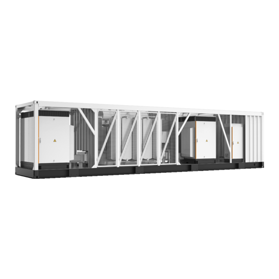
S S G G 4 4 9 9 5 5 0 0 H H V V - - M M V V I I n n p p u u t t ( ( D D C C ) ) Max.
Page 115
System Manual 13 Appendix Oil type Mineral oil (PCB free) or degradable oil on request P P r r o o t t e e c c t t i i o o n n & & F F u u n n c c t t i i o o n n DC input protection Load break switch + fuse Inverter output protection...
Page 116
13 Appendix System Manual T T y y p p e e D D e e s s i i g g n n a a t t i i o o n n S S G G 6 6 2 2 5 5 0 0 H H V V - - M M V V S S G G 6 6 8 8 0 0 0 0 H H V V - - M M V V MPP voltage range 875~1300 V...
System Manual 13 Appendix T T y y p p e e D D e e s s i i g g n n a a t t i i o o n n S S G G 6 6 2 2 5 5 0 0 H H V V - - M M V V S S G G 6 6 8 8 0 0 0 0 H H V V - - M M V V Surge protection DC Type I + II / AC Type II...
Unforeseen calamity or force majeure • The use of supplied software produced by Sungrow Power Supply Co., Ltd. is subject to the following conditions: Sungrow Power Supply Co., Ltd. assumes no liability for direct or indirect damages •...
Page 119
System Manual 13 Appendix China (HQ) Australia Sungrow Australia Group Pty. Ltd. Sungrow Power Supply Co., Ltd Hefei Sydney +86 551 65327834 +61 2 9922 1522 service@sungrowpower.com service@sungrowpower.com.au Brazil France SungrowDo Brasil Sungrow France – Siege Social Sao Paulo Paris +55 11 2366 1957 latam.service@sa.sungrowpower.com...
Page 120
13 Appendix System Manual Romania Turkey Service Partner - Elerex Sungrow Deutschland GmbH Turkey Istanbul Representative Bureau +40 241762250 Istanbul service.romania@sungrow.co +90 2127318883 service.turkey@sungrow.co U.S.A, Mexico Sungrow Power UK Ltd. Sungrow USA Corporation Milton Keynes PhoenixArizona +44 (0) 0908 414127 +1833 7476937 service.uk@sungrow.co...