
Related Manuals for Zodiac HPO


Summary of Contents for Zodiac HPO
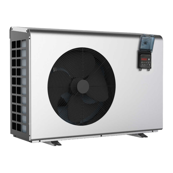
- Page 1 Instructions for installation and use - English Heat pump Translation of the original instructions in French More documents on: www.zodiac.com H0721600_REVA - 2021/05...
- Page 2 WARNINGS This symbol indicates that further This symbol indicates that the information is available in the appliance uses R32, a slow- User Manual or in the Installation burning refrigerant. Manual. This symbol indicates that This symbol indicates that the a maintenance technician User Manual must be read must handle this equipment carefully.
- Page 3 • Deactivating, eliminating or by-passing any of the safety mechanisms integrated into the appliance shall automatically void the warranty, in addition to the use of spare parts manufactured by unauthorised third-party manufacturers. • Do not spray insecticide or any other chemical (flammable or non-flammable) in the direction of the appliance, as this may damage the body and cause a fire.
- Page 4 • The appliance must be stored in a room without any permanent ignition source (such as open flames, operating gas appliance or operating electric heating). • No not perforate or incinerate. • Please note that R32 refrigerant may give off a certain odour. •...
- Page 5 refrigerant has been drained. • The label must be dated and signed. • For appliances containing a flammable refrigerant, check that labels are placed on the equipment stating that it contains a flammable refrigerant. RECOVERY • When draining the refrigerant for maintenance or decommissioning, best practices should be followed in order to safely drain all of the refrigerant.
-
Page 6: Table Of Contents
CONTENTS ❶ Installation 1.1 I Selecting the location 1.2 I Hydraulic connections 1.3 I Accessing the electrical terminal blocks 1.4 I Power supply connections 1.5 I Connecting options ❷ Use 2.1 I Operating principle 2.2 I User interface presentation 2.3 I Operation 2.4 I User functions ❸... -
Page 7: ❶ Installation
❶ Installation 1.1 I Selecting the location • The appliance must be installed at least 2 metres from the pool's edges. • Do not lift the appliance by the body; use its base. • Installation is only permitted outdoors: provide for a clear space around the appliance as shown in the diagram under §... -
Page 8: I Hydraulic Connections
1.2 I Hydraulic connections • The device will be connected with a Ø50 PVC pipe, using the connectors supplied (see § “5.1 I Description”), to the pool's filtration circuit, after the filter and before the water treatment system. • Respect the direction of hydraulic connection. •... -
Page 9: I Accessing The Electrical Terminal Blocks
1.3 I Accessing the electrical terminal blocks Unscrew the 3 screws on the Pass the cables through the cable technical access door at the rear of Remove the technical access door. glands on the technical access door. the appliance. 1.4 I Power supply connections •... -
Page 10: I Connecting Options
1.5 I Connecting options Connecting the "Heating priority" and "remote control" options: • Before any work inside the appliance, you must cut the appliance’s electricity supply as there is a risk of electric shock which may cause material damage, serious injury or even death. •... -
Page 11: ❷ Use
❷ Use 2.1 I Operating principle 2.1.1 General operation Your heat pump uses the calories (heat) in the air to heat up your pool's water. The process to heat your pool's water to the temperature you want may take a few days as it depends on the weather conditions, the heat pump's power and the difference between the water temperature and the temperature you want. -
Page 12: I Operation
Description Steady Flashing Operating in "HEATING" "HEATING" mode Disabled mode Operating in "COOLING" mode Disabled "COOLING" mode "HEATING & COOLING" Operating in "HEATING Disabled mode & COOLING" mode "BOOST" mode Operating at full power "BOOST" mode Disabled activated in "SMART" mode Operating at medium "SMART"... -
Page 13: I User Functions
• Reduce the temperature setpoint to below the water temperature to check that the heat pump stops operating. • Switch off the heat pump by pressing and check that it stops. 2.4 I User functions 2.4.1 "Automatic keypad lock" function The "automatic keypad lock"... - Page 14 2.4.4 "BOOST", "SMART" and "SILENCE" mode The heat pump can adapt its power to suit the pool temperature and weather conditions. In doing so, it obtains maximal energy efficiency at a very low noise level. Silence Boost Power "BOOST" mode "SMART"...
-
Page 15: ❸ Maintenance
❸ Maintenance 3.1 I Winterising • Even though the appliance can be used year round, if it will not be used for the winter months, a suitable winterising procedure must be implemented to prevent damage to the condenser. Damage caused by improper winterising of the appliance when not in use is not covered by the warranty. - Page 16 into the surrounding space. Before starting the work, the area around the equipment must be examined to check for all fire or ignition risks. "No smoking" signs must be displayed. Area ventilation • Before accessing the unit in any manner whatsoever with the intention of performing any maintenance task, check that the area is open and well-ventilated.
- Page 17 • If a leak is suspected, all naked flames must be removed/extinguished. • If a refrigerant leak is detected and requires soldering, the entire quantity of refrigerant must be removed from the system or isolated (by way of shut-off valves) in part of the system located away from the leak. Removal and discharge •...
-
Page 18: ❹ Troubleshooting
• Clean the outside of the appliance using a solvent-free product; a specific "PAC NET" cleaning kit is available as an accessory in the Zodiac® catalogue for this purpose (see § “5.1 I Description”). 3.2.3 Maintenance to be carried out by a qualified technician •... -
Page 19: I Error Code Display
• Check that the automatic water filling controller (see diagram in § "2.3 I Operation") is not stuck in the open position: this will keep supplying cold water into the pool and will prevent the The appliance temperature from rising. is working •... - Page 20 Low-pressure sensor broken. Replace the low-pressure sensor. EE02 Insufficient level of refrigerant. Add refrigerant. Low pressure protection Ambient temperature and input Send the pump to the retailer for a water temperature too low. detailed inspection. Flow switch incorrectly positioned. Re-make the connections. Insufficient water flow.
- Page 21 Programming error, disconnect The data is incorrect. the power supply and start after 3 minutes. The connection is faulty. EE11 Check the connection. Faulty motherboard for IPM module Accumulation of liquid and gas. Check the power supply voltages Faulty compressor or printed circuit Check the phases.
- Page 22 The power supply is incorrect. Replace the printed circuit board. EE22 High voltage protection The power board is faulty. Replace the printed circuit board. The power board is faulty. Check the printed circuit board. EE23 Accumulation of liquid and gas. Check the power supply voltages Compressor start-up error The voltage is unstable.
-
Page 23: I Wiring Diagrams
4.3 I Wiring diagramsWiring diagrams 4.3.1 HPO-6, HPO-8, HPO-9, HPO-11, HPO-14... - Page 24 4.3.2 HPO-18...
-
Page 25: ❺ Specifications
❺ Specifications 5.1 I Description Ø50 PVC connectors x2 Anti-vibration pads x4 Winterising cover Heating priority Remote control kit Condensate drainage connector x2 Hose x2 PAC NET (cleaning product) : Included : Available as an accessory... -
Page 26: I Technical Specifications
5.2 I Technical specifications HPO-6 HPO-8 HPO-9 HPO-11 HPO-14 HPO-18 Heating: from -12°C to 43°C/Cooling: from 15°C to 43°C Operating temperatures water Heating: from 6°C to 41°C/Cooling: from 6°C to 35°C Power output 9 - 1.9 10.5 - 2.1 13.5 - 2.5 16.5 - 3... -
Page 27: I Dimensions And Marking
5.3 I Dimensions and marking : Grid : User interface : Pool water inlet Front Rear : Pool water outlet Bottom HPO-8 HPO-14 Model HPO-6 HPO-9 HPO-18 HPO-11 1074 446.5 * Dimensions in mm. - Page 28 ©2021 Zodiac Pool Systems LLC. All rights reserved. ZODIAC® is a registered trademark of Zodiac International, ©2021 Zodiac Pool Systems LLC. All rights reserved. ZODIAC® is a registered trademark of Zodiac International, S.A.S.U., used under license. All other trademarks are the property of their respective owners.
Need help?
Do you have a question about the HPO and is the answer not in the manual?
Questions and answers