Advertisement
01/13 Rev. 5.05-01
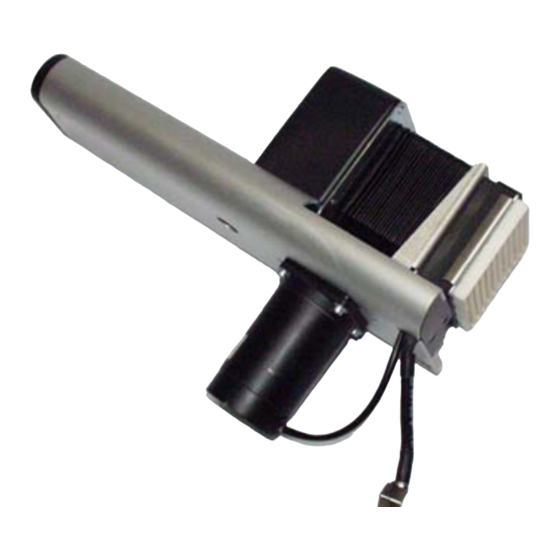
Mounting and setting the LTSI
Required Components .................................. 2
Fitting the Applicator ..................................... 3
Setting the Applicator .................................... 4
Setting the Dispense Position ................... 6
USER / SERCICE MANUAL
LTSI
Advertisement
Table of Contents

Related Manuals for Novexx Solutions LTSI


Summary of Contents for Novexx Solutions LTSI
- Page 1 01/13 Rev. 5.05-01 USER / SERCICE MANUAL LTSI Mounting and setting the LTSI Required Components ........2 Fitting the Applicator ........3 Setting the Applicator ........4 „Must“-parameters ........4 „Can“-parameters ........4 Adjusting the Applicator Home Position ..5...
- Page 2 LTSI 80/200 (fig.) Basic module A4788 LTSI 80/400 Aluminium plate (with screws 2x DIN912 M5x12 A2661 and 2x DIN912 M8x20) [Tab. 1] Required components to fit the LTSI to an 64-xx. The basic module is only required in one version.
- Page 3 3. Bolt the adapter plate [2A] onto the mounting flange (2x M5x16). [7] Adapter plate (A) ready mounted. 4. Bolt the applicator to the aluminium plate (2x M8x20 with lock washers) [3]. 5. Plug the applicator cable to the printer [3A]. [8] LTSI ready mounted and connected.
- Page 4 01/13 Rev. 5.05-01 USER / SERVICE MANUAL Mounting and setting the LTSI LTSI Setting the Applicator Setting the Applicator WARNING! Danger of getting hands crushed at the following locations: • Between applicator pressure plate and printer dispensing edge. • Between applicator pressure plate and conveyor (if applicable).
- Page 5 01/13 Rev. 5.05-01 USER / SERVICE MANUAL Mounting and setting the LTSI LTSI Setting the Applicator Adjusting the Applicator Home Position After fitting the applicator, the home position of the ap- plicator must be checked and adjusted if necessary. When viewed from the side, the applicator plate must stand slightly above and in front of the dispensing edge [4].
- Page 6 01/13 Rev. 5.05-01 USER / SERVICE MANUAL Mounting and setting the LTSI LTSI Setting the Applicator Setting the Dispense Position Dispensed label Dispense position The label can either be dispensed so that it is entirely free from the carrier material, or it can remain adhering to the carrier material via a small strip when the feed stops [6].
Need help?
Do you have a question about the LTSI and is the answer not in the manual?
Questions and answers