Table of Contents
Advertisement
Quick Links
MAN – FD320LIFT-LP Ver HD
Manufactured by MILIC, LLC with marketing support from Flight Display Systems.
This product does not have FAA PMA approval.
TECHNICAL SUPPORT
+1 (678) 867-6717, or
www.FlightDisplay.com
All manuals and user guides at all-guides.com
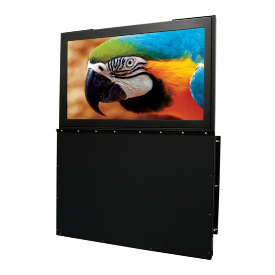
32" High-Definition LCD with Low-Profile Motorized Lift
Rev:
FD320LIFT-LP Ver HD
Installation and Operation Manual
Revision Date:
08/27/2012
C
Page 1 of 22
Advertisement
Table of Contents

Related Manuals for Flight Display Systems FD320LIFT-LP


Summary of Contents for Flight Display Systems FD320LIFT-LP
- Page 1 Page 1 of 22 FD320LIFT-LP Ver HD Installation and Operation Manual 32” High-Definition LCD with Low-Profile Motorized Lift Manufactured by MILIC, LLC with marketing support from Flight Display Systems. This product does not have FAA PMA approval. TECHNICAL SUPPORT +1 (678) 867-6717, or...
- Page 2 MAN – FD320LIFT-LP Ver HD Page 2 of 22 FD320LIFT-LP Ver HD 32" High-Definition LCD with Low-Profile Motorized Lift © 2009 Flight Display Systems. All Rights Reserved. Flight Display Systems 1765 Grassland Parkway Alpharetta, GA 30004 +1 (678) 867-6717 Phone +1 (678) 867-6742 Fax sales@flightdisplay.com...
-
Page 3: Table Of Contents
All manuals and user guides at all-guides.com Rev: Revision Date: 08/27/2012 MAN – FD320LIFT-LP Ver HD Page 3 of 22 Table of Contents General Information ........................4 1. Front View ..........................4 2. Additional Information ....................4 Specifications ..........................5 Installation Instructions ......................6 1. Power ..........................6 2. -
Page 4: General Information
Do not apply excessive downward force on the top of the lift/monitor, this could overstress the cable and damage the unit. The FD320LIFT-LP Ver HD utilizes a state of the art digital video decoding chipset for the analog video input. There are five video source inputs available. They are in order... -
Page 5: Specifications
MAN – FD320LIFT-LP Ver HD Page 5 of 22 The FD320LIFT-LP Ver HD can also be connected to existing video switchers and simply accept a composite video input from a selector interface box. In this case multiple input sources can be selected and displayed on the monitor. You would only use the IR remote to set up the screen during installation. -
Page 6: Installation Instructions
Adjusting Stowed Position Height The FD320LIFT-LP Ver HD down limit can be adjusted up to 1-1/2”. The unit is pre- adjusted to the lowest stow position. Access the adjustment bolt through the opening on the top of the lift as shown below. -
Page 7: Wiring Suggestions
Caution: Limit switches do not function when manually raising or lowering the display. Be sure not to exceed upper or lower travel limits, this could result in permanent damage to the FD320LIFT-LP Ver HD. Wiring Suggestions All shields should be grounded to the connector at the source, and floating at the display. -
Page 8: Vga Wiring
Rev: Revision Date: 08/27/2012 MAN – FD320LIFT-LP Ver HD Page 8 of 22 Similar aviation coaxial cable can be used from other vendors, as well. Some aircraft are prone to AC noise - we recommend adding to the composite source a 75Ohm video isolation transformer such as Deerfield Laboratory, Inc. -
Page 9: Rs-485 Wiring
ECS manufactures an HDMI cable that is terminated at the factory. It is ordered as part number 600-19786-XXX, where XXX is the length in inches for the desired cable. Also available from Flight Display Systems is an HDMI to Cat5e/6 converter, which drastically reduces the cost of cabling while increasing the maximum allowable cable run to 100ft for High-Definition Video. -
Page 10: Power & Ground Wiring
All manuals and user guides at all-guides.com Rev: Revision Date: 08/27/2012 MAN – FD320LIFT-LP Ver HD Page 10 of 22 Power and Ground Wiring This is a 28VDC monitor that requires 10 amps of power to operate. The rated current of the equipment and associated voltage drop should be taken into consideration when selecting wire gauge. -
Page 11: Power/Video
All manuals and user guides at all-guides.com Rev: Revision Date: 08/27/2012 MAN – FD320LIFT-LP Ver HD Page 11 of 22 Power/Video Pin out for High Density DB-25 (J1 – Power/Control) Connector P/N: M24308/2-283 or Equivalent Crimp Contacts P/N: M39029/63-368 or Equivalent... - Page 12 All manuals and user guides at all-guides.com Rev: Revision Date: 08/27/2012 MAN – FD320LIFT-LP Ver HD Page 12 of 22 Power/Video Pin out for High Density DB-9 (J2 – Video) Connector P/N: M24308/2-286 or Equivalent Crimp Contacts P/N: M39029/57-354 or Equivalent...
-
Page 13: Rs-485 Control
All manuals and user guides at all-guides.com Rev: Revision Date: 08/27/2012 MAN – FD320LIFT-LP Ver HD Page 13 of 22 RS-485 Control (Optional) RS-485 is a two-wire communication interface that allows an external device such as a computer or switching unit to control the monitor’s functions remotely. Up to 99... -
Page 14: Command Sets
All manuals and user guides at all-guides.com Rev: Revision Date: 08/27/2012 MAN – FD320LIFT-LP Ver HD Page 14 of 22 Command sets for controlling the monitor: Below are the command sets to control the power, source selection, and backlight brightness. The 13 characters below are shown in hexadecimal. The communication system must be set up for 19200 Baud, no parity, 8 bits of data, and 1 stop bit. -
Page 15: Rs-485 Network
All manuals and user guides at all-guides.com Rev: Revision Date: 08/27/2012 MAN – FD320LIFT-LP Ver HD Page 15 of 22 RS-485 Network: If there is more than one monitor connected to the aircraft’s RS-485 controller system, then it is strongly recommended to connect the system in series, or daisy-chain, and terminate the twisted pairs with a 120 OHM resistor. -
Page 16: Operation Instructions
No pilot or aircrew action is necessary during flight or ground operation. The passengers will be able to change the video output from the FD320LIFT-LP Ver HD using the video source select button with the included IR remote. Point the IR remote towards the top of the LCD to cycle thru the different sources. - Page 17 All manuals and user guides at all-guides.com Rev: Revision Date: 08/27/2012 MAN – FD320LIFT-LP Ver HD Page 17 of 22...
-
Page 18: Troubleshooting
All manuals and user guides at all-guides.com Rev: Revision Date: 08/27/2012 MAN – FD320LIFT-LP Ver HD Page 18 of 22 Troubleshooting Video Noise Check for an incorrect ground in the installation wiring. See specific examples of video noise below, or visit http://flightdisplay.com/Grounding.pdf... -
Page 19: Technical Drawing
All manuals and user guides at all-guides.com Rev: Revision Date: 08/27/2012 MAN – FD320LIFT-LP Ver HD Page 19 of 22 Technical Drawing... -
Page 20: Technical Support
Email: sales@flightdisplay.com For further product information, technical data and sample wiring diagrams, please click on the Dealers section of our web site at www.flightdisplay.com Instructions for Continued Airworthiness The FD320LIFT-LP Ver HD is designed not to require regular general maintenance. -
Page 21: Warranty
6717 to obtain assistance. If the return of the unit to the factory is required, an RMA number will be issued at that time. Flight Display Systems will, upon receipt of the failed hardware, remanufacture or replace the unit at our discretion. -
Page 22: Log Of Revisions
All manuals and user guides at all-guides.com Rev: Revision Date: 08/27/2012 MAN – FD320LIFT-LP Ver HD Page 22 of 22 Log of Revisions Date Page Description 11/06/2009 Initial Release 01/06/2010 Amp Revise 08/27/2012 Update format, warranty and non-PMA info...
Need help?
Do you have a question about the FD320LIFT-LP and is the answer not in the manual?
Questions and answers