
Related Manuals for Flight Display Systems FD151CV-LP


Summary of Contents for Flight Display Systems FD151CV-LP
- Page 1 All manuals and user guides at all-guides.com FD151CV-LP Installation and Operation Manual 15.1” Low Profile LCD TECHNICAL SUPPORT 678-867-6717, or www.FlightDisplay.com...
- Page 2 All manuals and user guides at all-guides.com FD151CV-LP 15.1" Low Profile LCD © 2006 Flight Display Systems. All Rights Reserved. Flight Display Systems 1765 Grassland Parkway Alpharetta, GA 30004 678-867-6717 Phone 678-867-6742 Fax sales@flightdisplay.com www.flightdisplay.com For the most current copy of all product manuals, please visit our website at www.flightdisplay.com...
-
Page 3: Table Of Contents
All manuals and user guides at all-guides.com Table of Contents General Information Front View ...................... 1 Additional Information ................1 Specifications..................... 2 Installation Instructions Power ......................2 Video Wiring Suggestions ................3 S-Video/Composite and Audio Wiring............. -
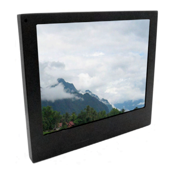
Page 4: General Information
Front View Additional Information The FD151CV-LP utilizes a state of the art digital video decoding chipset for the analog video input. The video sources in order of picture quality are VGA (computer graphics like moving maps), and Composite Video (DVD, camera or VCR). -
Page 5: Specifications
Section 21 Category B Installation Instructions All cabin entertainment equipment, such as the FD151CV-LP, should be installed on a non-essential bus and have a dedicated circuit breaker. It is a requirement that a switch be installed in the cockpit so that the pilot can de- energize the entertainment system should it become necessary. -
Page 6: Video Wiring Suggestions
All manuals and user guides at all-guides.com FD151CV-LP Video Wiring Suggestions All shields should be grounded to the connector at the source, and floating at the display. Avoid routing video wiring parallel to: • AC wiring • Strobe wiring •... -
Page 7: Vga Wiring
All manuals and user guides at all-guides.com VGA Wiring Recommended cable for VGA purpose is ECS P/N 453005. This is a single shielded cable containing 5 separate coaxial cables, color-coded to match the functions of the wires. We recommend coax cables be terminated using solder sleeve coaxial cable terminators such as Raychem Part Number CWT-4174-W122-5/9. -
Page 8: Power And Ground Wiring
All manuals and user guides at all-guides.com FD151CV-LP Power and Ground Wiring This is a 28VDC monitor that requires 1.5 amps of power to operate. To operate properly this monitor requires an input voltage of 18-29VDC. The rated current of the equipment and associated voltage drop should be taken into consideration when selecting wire gauge. -
Page 9: Pinout For High Density Db-15
All manuals and user guides at all-guides.com Pinout for High Density DB-15 There is one High Density DB-15 on the rear of the display, which connects Power, Composite Video #1, Composite Video #2 and VGA connections. Part Numbers for DB-15 connectors, manufactured by Tyco or Amp. High density, D-sub, 15 contact receptacle (female) P/N 748565-1 HD15F pins... -
Page 10: Operation Instructions
No pilot or aircrew action is necessary during flight or ground operation. The passengers will be able to change the video output from the FD151CV-LP using the video source select button on the display, or remotely throughout the cabin with the included IR remote. -
Page 11: Remote Control
All manuals and user guides at all-guides.com Remote Control The remote control included with the FD151CV-LP contains the same functionality available on the display buttons, to include power, source, menu, and directional arrows. 8 Revision D, November 2008 ... -
Page 12: Troubleshooting
All manuals and user guides at all-guides.com FD151CV-LP Troubleshooting Video Noise Check for an incorrect ground in the installation wiring. See specific examples of video noise below, or visit http://flightdisplay.com/Grounding.pdf VGA Shadowing Most of shadowing problems are due to shielding on the wire. Locate the point where all of the shields are connected. -
Page 13: Color Distortion
Email: sales@flightdisplay.com For further product information, technical data and sample wiring diagrams, please click on the Dealers section of our web site at www.flightdisplay.com Instructions for Continued Airworthiness The FD151CV-LP is designed not to require regular general maintenance. 10 Revision D, November 2008 ... -
Page 14: Warranty Information
867-6717 to obtain assistance. If the return of the unit to the factory is required, an RMA number will be issued at that time. Flight Display Systems will, upon receipt of the failed hardware, remanufacture or replace the unit at our discretion. -
Page 15: Assembly Drawing
All manuals and user guides at all-guides.com Assembly Drawing 12 Revision D, November 2008 ... - Page 16 All manuals and user guides at all-guides.com FD151CV-LP 13 Revision D, November 2008 ...
-
Page 17: Index
All manuals and user guides at all-guides.com Index Button Controls ......... 7 Shadowing ......... 9 Coaxial Cable........3 Shields ..........3, 9 Color Distortion ......10 Support......... 9, 10 Continued Airworthiness ....10 VGA ............ 4 DB-15 ..........6 Warranty .......... 11 DO-160E ......... -
Page 18: Log Of Revisions
All manuals and user guides at all-guides.com FD151CV-LP Log of Revisions Date Page Description 01/25/2007 05/21/2007 Added remote control information. 03/05/2008 Changed button order. Updated VGA, Power & Ground, Pinout and Assembly 11/26/2008 drawings 15 Revision D, November 2008 ...
Need help?
Do you have a question about the FD151CV-LP and is the answer not in the manual?
Questions and answers