Table of Contents

Related Manuals for Flight Display Systems FD102CV


Summary of Contents for Flight Display Systems FD102CV
- Page 1 All manuals and user guides at all-guides.com Document Number: Rev: Revision Date: 2/1/2012 MAN – FD102CV Page 1 of 16 FD102CV Installation and Operation Manual 10.2” Widescreen LCD TECHNICAL SUPPORT 678-867-6717, or www.FlightDisplay.com...
- Page 2 Document Number: Rev: Revision Date: 2/1/2012 MAN – FD102CV Page 2 of 16 FD102CV 10.2” Widescreen LCD © 2006 Flight Display Systems. All Rights Reserved. Flight Display Systems 1765 Grassland Parkway Alpharetta, GA 30004 678-867-6717 Phone 678-867-6742 Fax sales@flightdisplay.com www.flightdisplay.com For the most current copy of all product manuals, please visit our website at www.flightdisplay.com...
-
Page 3: Table Of Contents
All manuals and user guides at all-guides.com Document Number: Rev: Revision Date: 2/1/2012 MAN – FD102CV Page 3 of 16 Table of Contents General Information ........................4 1. Front View ..........................4 2. Additional Information ....................4 Specifications ..........................5 Installation Instructions ......................5 1. Power ..........................5 Wiring Instructions ........................6... -
Page 4: General Information
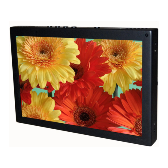
Front View Additional Information The FD102CV can be connected to existing video switchers and can take a composite video input from a selector interface box. Multiple input sources can be selected and displayed on the monitor. The FD102CV is made of all metal components. DO-160 testing has been completed and is available upon request. -
Page 5: Specifications
Section 21, Category B Installation Instructions All cabin entertainment equipment, such as the FD102CV, should be installed on a non- essential bus and have a dedicated circuit breaker. It is a requirement that a switch be installed in the cockpit so that the pilot can de-energize the entertainment system should it become necessary. -
Page 6: Wiring Instructions
All manuals and user guides at all-guides.com Document Number: Rev: Revision Date: 2/1/2012 MAN – FD102CV Page 6 of 16 Wiring Suggestions All shields should be grounded to the connector at the source, and floating at the display. Avoid routing video wiring parallel to: ... -
Page 7: Vga Wiring
Document Number: Rev: Revision Date: 2/1/2012 MAN – FD102CV Page 7 of 16 VGA Wiring Recommended cable for VGA purpose is ECS P/N 453005. This is a single shielded cable containing 5 separate coaxial cables, color-coded to match the functions of the wires. -
Page 8: Power/Video
All manuals and user guides at all-guides.com Document Number: Rev: Revision Date: 2/1/2012 MAN – FD102CV Page 8 of 16 Power/Video Pin out for P1 (High Density DB-15 Receptacle) Connector P/N: M24308/2-286 or Equivalent Crimp Contacts P/N: M39029/57-354 or Equivalent... -
Page 9: Operations Instructions
MAN – FD102CV Page 9 of 16 Operation Instructions The FD102CV is continuously on but can be de-energized by removing power from the entertainment system. No pilot or aircrew action is necessary during flight or ground operation. Passengers can change the video output from the FD102CV using the video source select switch on the LCD monitor, or remotely throughout the cabin with the included IR remote. -
Page 10: Remote Control Buttons
Document Number: Rev: Revision Date: 2/1/2012 MAN – FD102CV Page 10 of 16 Remote Control Buttons The remote control included with the FD102CV contains the same functionality available on the display buttons, to include power, source, menu, and directional arrows. -
Page 11: Technical Drawing
All manuals and user guides at all-guides.com Document Number: Rev: Revision Date: 2/1/2012 MAN – FD102CV Page 11 of 16 Technical Drawing... -
Page 12: Troubleshooting
All manuals and user guides at all-guides.com Document Number: Rev: Revision Date: 2/1/2012 MAN – FD102CV Page 12 of 16 Troubleshooting Video Noise Check for an incorrect ground in the installation wiring. See specific examples of video noise below, or visit http://flightdisplay.com/Grounding.pdf... - Page 13 All manuals and user guides at all-guides.com Document Number: Rev: Revision Date: 2/1/2012 MAN – FD102CV Page 13 of 16 Intermittent or failed power: Inspect connection on the monitor side. Inspect the connection on the aircraft side. Confirm proper rating on fuses.
-
Page 14: Technical Support
2/1/2012 MAN – FD102CV Page 14 of 16 Technical Support Should you have any questions concerning this product or other Flight Display Systems products, please contact our Product Support representatives at (678) 867-6717. Flight Display Systems 1765 Grassland Parkway Alpharetta, GA 30004... -
Page 15: Warranty
If the return of the unit to the factory is required, an RMA number will be issued at that time. Flight Display Systems will, upon receipt of the failed hardware, remanufacture or replace the unit at our discretion. -
Page 16: Log Of Revisions
2/1/2012 MAN – FD102CV Page 16 of 16 Log of Revisions Date Page Description 01/25/2007 03/28/2007 Added info regarding FD102CV (28V) Fixed page numbering. 04/11/2007 Changed required amperage to 2 Amps. 04/09/2008 Updated DWG. 02/11/2009 2,10 Updated specs, warranty info...
Need help?
Do you have a question about the FD102CV and is the answer not in the manual?
Questions and answers