Table of Contents
Advertisement
Quick Links
MAN – FD102CV-LP-S
Manufactured by MILIC, LLC with marketing support from Flight Display Systems.
This product does not have FAA PMA approval.
TECHNICAL SUPPORT
678-867-6717, or
www.FlightDisplay.com
All manuals and user guides at all-guides.com
Rev:
B
Installation and Operation Manual
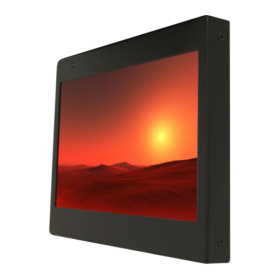
Low Profile 10.2" Widescreen LCD
Revision Date:
08/24/2012
Page 1 of 15
FD102CV-LP-S
Advertisement
Table of Contents

Related Manuals for Flight Display Systems FD102CV-LP-S


Summary of Contents for Flight Display Systems FD102CV-LP-S
- Page 1 MAN – FD102CV-LP-S Page 1 of 15 FD102CV-LP-S Installation and Operation Manual Low Profile 10.2” Widescreen LCD Manufactured by MILIC, LLC with marketing support from Flight Display Systems. This product does not have FAA PMA approval. TECHNICAL SUPPORT 678-867-6717, or www.FlightDisplay.com...
- Page 2 Rev: Revision Date: 08/24/2012 MAN – FD102CV-LP-S Page 2 of 15 FD102CV-LP-S Low Profile 10.2” Widescreen LCD © 2010 Flight Display Systems. All Rights Reserved. Flight Display Systems 1765 Grassland Parkway Alpharetta, GA 30004 678-867-6717 Phone 678-867-6742 Fax sales@flightdisplay.com www.flightdisplay.com For the most current copy of all product manuals, please visit our website at www.flightdisplay.com...
-
Page 3: Table Of Contents
All manuals and user guides at all-guides.com Rev: Revision Date: 08/24/2012 MAN – FD102CV-LP-S Page 3 of 15 Table of Contents General Information ........................4 1. Front View ..........................4 2. Additional Information ....................4 Specifications ..........................5 Installation Instructions ......................5 1. Power ..........................5 Wiring Instructions ........................6... -
Page 4: General Information
Moving Maps), and two (2x) Composite Video (DVD, Camera or VCR). Both NTSC and PAL formats are auto-detected. The FD102CV-LP-S can also be connected to existing video switchers and can take a composite video input from a selector interface box. In this case, multiple input sources... -
Page 5: Specifications
Section 21, Category B Installation Instructions All cabin entertainment equipment, such as the FD102CV-LP-S, should be installed on a non-essential bus and have a dedicated circuit breaker. It is a requirement that a switch be installed in the cockpit so that the pilot can de-energize the entertainment system should it become necessary. -
Page 6: Wiring Instructions
All manuals and user guides at all-guides.com Rev: Revision Date: 08/24/2012 MAN – FD102CV-LP-S Page 6 of 15 Wiring Suggestions All shields should be grounded to the connector at the source, and floating at the display. Avoid routing video wiring parallel to: ... -
Page 7: Vga Wiring
All manuals and user guides at all-guides.com Rev: Revision Date: 08/24/2012 MAN – FD102CV-LP-S Page 7 of 15 VGA Wiring Recommended cable for VGA purpose is ECS P/N 453005. This is a single shielded cable containing 5 separate coaxial cables, color-coded to match the functions of the wires. -
Page 8: Power/Video
All manuals and user guides at all-guides.com Rev: Revision Date: 08/24/2012 MAN – FD102CV-LP-S Page 8 of 15 Power/Video Pin out for P1 (High Density DB-15 Receptacle) There is one High Density DB-15 on the rear of the display, which connects Power, Composite Video #1, Composite Video #2 and VGA connections. -
Page 9: Operations Instructions
MAN – FD102CV-LP-S Page 9 of 15 Operation Instructions The FD102CV-LP-S is continuously on but can be de-energized by removing power from the entertainment system. No pilot or aircrew action is necessary during flight or ground operation. Passengers can change the video output from the FD102CV-LP-S using the video source select switch on the included IR remote. -
Page 10: Remote Control Buttons
All manuals and user guides at all-guides.com Rev: Revision Date: 08/24/2012 MAN – FD102CV-LP-S Page 10 of 15 Remote Control Buttons The IR LED, located on the top of the monitor, must be visible to the remote for wireless operation. Refer to button controls on previous page for remote control button functions. -
Page 11: Troubleshooting
All manuals and user guides at all-guides.com Rev: Revision Date: 08/24/2012 MAN – FD102CV-LP-S Page 11 of 15 Troubleshooting Video Noise Check for an incorrect ground in the installation wiring. See specific examples of video noise below, or visit http://flightdisplay.com/Grounding.pdf VGA Shadowing Most of shadowing problems are due to shielding on the wire. -
Page 12: Technical Support
08/24/2012 MAN – FD102CV-LP-S Page 12 of 15 Technical Support Should you have any questions concerning this product or other Flight Display Systems products, please contact our Product Support representatives at (678) 867-6717. Flight Display Systems 1765 Grassland Parkway Alpharetta, GA 30004... -
Page 13: Warranty
If the return of the unit to the factory is required, an RMA number will be issued at that time. Flight Display Systems will, upon receipt of the failed hardware, remanufacture or replace the unit at our discretion. -
Page 14: Installation Drawings
All manuals and user guides at all-guides.com Rev: Revision Date: 08/24/2012 MAN – FD102CV-LP-S Page 14 of 15 Installation Drawing... -
Page 15: Log Of Revisions
All manuals and user guides at all-guides.com Rev: Revision Date: 08/24/2012 MAN – FD102CV-LP-S Page 15 of 15 Log of Revisions Date Page Description 11/17/2010 Initial Release 08/24/2012 Updated format, warranty and non-PMA info...
Need help?
Do you have a question about the FD102CV-LP-S and is the answer not in the manual?
Questions and answers