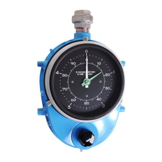
Endress+Hauser Float level gauge LT5 Operating Instructions Manual
Mechanical tank gauge for measuring liquid level
Hide thumbs
Also See for Float level gauge LT5:
- Operating instructions manual (96 pages) ,
- Operating instruction (78 pages) ,
- Brief operating instructions (56 pages)

Related Manuals for Endress+Hauser Float level gauge LT5


Summary of Contents for Endress+Hauser Float level gauge LT5
- Page 1 Products Solutions Services BA01264G/00/EN/06.22-00 71561893 2022-03-31 Operating Instructions Float level gauge LT5 Mechanical tank gauge for measuring liquid level...
- Page 2 Float level gauge LT5 Order code: XXXXX-XXXXXX Ser. no.: XXXXXXXXXXXX Ext. ord. cd.: XXX.XXXX.XX Serial number www.endress.com/deviceviewer Endress+Hauser Operations App A0023555 Endress+Hauser...
-
Page 3: Table Of Contents
Delivery examples ..... 11 10.3 Endress+Hauser services ....85 10.4 Return . -
Page 4: Document Information
Document information Float level gauge LT5 Document information Document function These Operating Instructions contain all the information that is required in various phases of the life cycle of the device: from product identification, incoming acceptance and storage, to mounting, connection, operation and commissioning through to troubleshooting, maintenance and disposal. - Page 5 Float level gauge LT5 Document information Flat blade screwdriver Torx screwdriver Allen key Open-ended wrench 1.2.4 Symbols for certain types of information and graphics Permitted Procedures, processes or actions that are permitted Preferred Procedures, processes or actions that are preferred Forbidden...
-
Page 6: Documentation
Document information Float level gauge LT5 Documentation The following documents can be found in the Download area of our website (www.endress.com/downloads). For an overview of the scope of the associated Technical Documentation, refer to the following: W@M Device Viewer (www.endress.com/deviceviewer): Enter the serial number from nameplate 1.3.1... -
Page 7: Basic Safety Instructions
Float level gauge LT5 Basic safety instructions Basic safety instructions Requirements for personnel The personnel for installation, commissioning, diagnostics and maintenance must fulfill the following requirements: ‣ Be specialists who are trained and have a relevant qualification for this specific function and task. -
Page 8: Operational Safety
Modifications to the device Unauthorized modifications to the device are not permitted and can lead to unforeseeable dangers: ‣ If modifications are nevertheless required, contact your Endress+Hauser Sales Center. Repair To ensure continued operational safety and reliability: ‣ Carry out repairs on the device only if they are expressly permitted. -
Page 9: Product Description
Product description Intended use Float level gauge LT5 is an important measuring instrument in the process industry. The structure does not require a power source and it is easy to install. Since it can be used for high-precision liquid level measurement and remote indication detection, it is ideal for the following operations: •... -
Page 10: List Of Material Standards
Product description Float level gauge LT5 Items Description Low-pressure Weight: 5.0 kg ρ: Liquid density (g/cm ): 0.65 ≤ ρ < 1.05 type Low-pressure Weight: 8.0 kg ρ: Liquid density (g/cm ): 1.05 ≤ ρ < 2.0 type High-pressure Weight: 8.3 kg ρ: Liquid density (g/cm... -
Page 11: Delivery Examples
Float level gauge LT5 Product description Delivery examples The packing method will differ based on the order code, etc. For the flange type, sheave elbows will be packed in a separate box. A0039945 1 Packing Gauge supporter Anchor hook... -
Page 12: Incoming Acceptance And Product
• Do the nameplate data match the ordering information on the delivery note? • If required (see nameplate): Are the Safety Instructions (XA) enclosed? If one of these conditions is not satisfied, contact your Endress+Hauser Sales Center. Product identification The following options are available for identification of the device: •... -
Page 13: Storage And Transport
Float level gauge LT5 Incoming acceptance and product identification Storage and transport 4.4.1 Storage conditions • Storage temperature: –20 to +70 °C (–4 to 158 °F) • Store the device in its original packaging. 4.4.2 Transport NOTICE The housing may become damaged or dislodged. -
Page 14: Installation
Installation Float level gauge LT5 Installation Dimensions of LT5 Dimensions of common components are used for the installation conditions. Contact your Endress+Hauser Sales Center if you are using different components. 5.1.1 Dimensions of LT5-1 (threaded, low-pressure type) 320 (12.6) (6.02) Ø400 (15.74) - Page 15 Float level gauge LT5 Installation (0.43) 32 (1.26) 90 (3.54) Ø52 (2.05) Ø42.7 (1.68) A0041188 4 Accessory 1. Unit of measurement mm (in) Gauge supporter (select from iron / SUS304) Top anchor (ADC6) Top anchor (SUS316 / socket welding type) Top anchor (PVC) (only flange type is available for PVC.)
- Page 16 Installation Float level gauge LT5 5.1.2 Dimensions of LT5-1 (flange, low-pressure type) (6.02) 320 (12.6) Ø400 (15.74) Ø410 (16.14) Ø140 (5.51) 440 (17.32) 4-M10 Ø140 (5.51) Ø400 (15.74) A0041187 6 Dimensions of LT5-1. Unit of measurement mm (in) Gauge head (ADC12) Float φ140 (SUS316)
- Page 17 Float level gauge LT5 Installation 300 (11.81) 330 (12.99) (3.15) 140 (5.51) Ø13 (3.15) (0.51) 4.5/4 (0.18/0.16) 40 (1.57) 32 (1.26) (5.51) Ø20 (0.79) 4 (0.16) 32 (1.26) 40 (1.57) A0041192 8 Accessory 2. Unit of measurement mm (in) Seal pot (select from aluminum+iron / SUS316;...
- Page 18 Installation Float level gauge LT5 5.1.3 Dimensions of LT5-4 (flange, medium-pressure type) Ø116 (4.57) 320 (12.6) (8.07) 141 (5.55) 4-M10 Ø20 (0.79) (5.31) Ø400 (15.74) Ø410 (16.14) 440 (17.32) (0.43) Ø13 (0.51) 4.5/4 32 (1.26) 90 (3.54) (0.18/0.16) 40 (1.57) 32 (1.26)
- Page 19 Float level gauge LT5 Installation Anchor hook (select from iron / SUS316) Gauge supporter (select from iron / SUS304) Flange (select from JIS 10K 40A RF / ASME NPS 1-1/2" Cl.150 RF/ JPI 40A 150 lbs RF) Endress+Hauser...
- Page 20 Installation Float level gauge LT5 5.1.4 Dimensions of LT5-6 (flange, high-pressure type) 236 (9.29) 350 (13.78) Ø116 (4.57) 141 (5.55) 4-M16 Ø20 (5.12) (0.79) Ø400 (15.74) Ø410 (16.14) 440 (17.32) 90 (3.54) (1.97) (0.35) Ø13 (0.51) 4.5/4 (0.18/0.16) 40 (1.57) 32 (1.26)
-
Page 21: Installation Preparation
Float level gauge LT5 Installation Installation preparation When installing LT, exercise the following precautions: • Select the gauge head installation site based on where it is the easiest to read the meter. • The float must be installed so that it is positioned near the tank sidewall. -
Page 22: Tools
Installation Float level gauge LT5 Tools Have the following tools ready to install LT5. Required tools LT5-1 LT5-1 Tools Intended use LT5-4 LT5-6 (threaded) (flange) 13 mm: Sheave elbow cover ● ● ● 24 mm: Sheave elbow cover ● 17 mm: Gauge head for a device supporter 〇... -
Page 23: Welding A Gauge Supporter
Float level gauge LT5 Installation Welding a gauge supporter See the following diagram for reference when welding a gauge supporter. Note that pipe supporters are not supplied. In LT5-6 (high-pressure gauge head), the distance between the tank' s external wall and the center of the gauge head is 15 mm (0.59 in) longer compared to that of... - Page 24 Installation Float level gauge LT5 265 (10.43) 25 (0.98) 50 (1.97) (3.54) 20 (0.79) 30 (1.18) R9 (0.35) 175 (6.89) A0041180 22 Gauge supporter (high pressure). Unit of measurement mm (in) Pipe supporter (not supplied) Center line of the mounting position Gauge supporter (based on the selected option SS400: t = 4.0 / SUS304: t = 4.0), mounting bolt...
-
Page 25: Guide Pipes
• Sheave elbow to tank roof Precautions regarding installation • Note that guide pipes and pipe supporters are not supplied by Endress+Hauser. • Ensure that any bends in guide pipes are 5 mm (0.17 in) or smaller. • The space (piping distance) between a sheave elbow and a sheave elbow must be no more than 2.5 m (8.2 ft). - Page 26 Installation Float level gauge LT5 5.5.2 Connecting guide pipes • Use PTFE sealing tape and gaskets on the unions and flanges in order to maintain airtightness against gas and rain. • Ensure that union connection is secure; otherwise, rain water may enter the gauge from the joint.
-
Page 27: Top Anchor And Anchor Hook
Float level gauge LT5 Installation Top anchor and anchor hook When installing an anchor hook, lower it so that it is perpendicular to the top anchor at the top of a tank, and use a plumb to determine the precise position. -
Page 28: Measuring Tape And Wire Lengths
Installation Float level gauge LT5 Measuring tape and wire lengths The lengths of the measuring tape and wire are longer than the actual measurement length and vary depending on each option. The following tables show the actual lengths according to options in 060 for each option of specification 070. However, note that the maximum length that can be displayed on the display of the gauge head simply corresponds to the measurement range. - Page 29 Float level gauge LT5 Installation 060 measurement Length (total Perforated Non- Spare parts range length) tape perforated (measurement tape length) 60 ft 167.31 ft 69.89 ft 98.42 ft Contact Endress+Hauser 100 ft 249.33 ft 108.26 ft 141.07 ft Contact Endress+Hauser 4.
- Page 30 Installation Float level gauge LT5 A0041195 27 Measuring tape and wire (example: option 1 for specification 070 and option 5 for specification 060) Perforated tape Non-perforated tape / wire In the above diagram, the maximum measurable distance is 22 mm, and there is up to 23 m of clearance.
-
Page 31: Sealing For Wetting Liquid And Gas Parts
Float level gauge LT5 Installation Sealing for wetting liquid and gas parts 5.8.1 List of materials Product Units Sealing material name Sealing material type Materials of packing/o-ring name LT5-1 Gauge head Rear cover Cover packing V#6502 Check shaft O-ring Sprocket shaft... -
Page 32: Material Certificates
Installation Float level gauge LT5 Material certificates When material certificates are required, order them when ordering the products. Certificates can be provided for the following parts. • Iron high-pressure gauge head (the flange is the same, as it is integrated with the gauge head), cover, magnet cover, check shaft (with no hoisting), plug •... -
Page 33: Installation Reference Diagram And Order
Float level gauge LT5 Installation 5.10 Installation reference diagram and order codes 5.10.1 For a cone roof tank (CRT) 950 (37.4) (8.66) (8.66) (9.84) Ø400 (15.74) (17.32) A0041196 28 Mounting on a cone roof tank. Unit of measurement mm (in) - Page 34 Installation Float level gauge LT5 Order code examples (LT5-111A031B11A111200000+PA) Items Target Code Specifications ntity Gauge head 0.01961 MPa/2.84 psi, aluminum (ADC12) Gauge head process connection Rc 1-1/2, union nut, SUS316, thread JISB0203 Display; cover Dial display: Acrylic Crank unit None...
- Page 35 Float level gauge LT5 Installation 5.10.2 Mounting on a tank top (for an underground tank) 153 (6.02) (17.32) A0041197 29 Mounting for an underground tank, unit. Unit of measurement mm (in) Anchor hook Top anchor Measuring tape Float Guide wire...
- Page 36 Installation Float level gauge LT5 Order code examples (LT5-111C022B11A100000000) Items Target Code Specifications ntity Gauge head 0.01961 MPa/2.84 psi, aluminum (ADC12) Gauge head process connection Rc 1-1/2, union nut, SUS316, thread JISB0203 Display; cover Reverse mounting, dial display, acrylic Crank unit...
- Page 37 Float level gauge LT5 Installation 5.10.3 Cone roof tank (with seal pot for CRT) 950 (37.4) (8.66) (8.66) 250 (9.84) Ø400 (15.74) (17.32) A0041198 30 Installation on a cone roof tank with seal pot for CRT. Unit of measurement mm (in)
- Page 38 Installation Float level gauge LT5 Order code examples (LT5-11AA023B1BA21A1000F0+PA) Items Target Code Specifications ntity Gauge head 0.01961 MPa/2.84 psi, aluminum (ADC12) Gauge head process connection 10K 40A RF, aluminum (AC4A), flange JIS B2220 Display; cover Dial display: Acrylic Crank unit...
- Page 39 Float level gauge LT5 Installation 5.10.4 Cone roof tank (with seal pot PVC for CRT) 950 (37.4) (8.66) (8.66) 250 (9.84) Ø400 (15.74) (17.32) (1.57) (0.28) Ø6 (0.24) A0041199 31 Installation on a cone roof tank with seal pot PVC for CRT. Unit of measurement mm (in)
- Page 40 Installation Float level gauge LT5 Order code examples (LT5-11AA025H1NC41A1000N0+PA) Items Target Code Specifications ntity Gauge head 0.01961 MPa/2.84 psi, aluminum (ADC12) Gauge head process connection 10K 40A RF, aluminum (AC4A), flange JIS B2220 Display; cover Dial display: Acrylic Crank unit...
- Page 41 Float level gauge LT5 Installation 5.10.5 Compact cone roof tank (guide pipe method) 950 (37.4) Ø140 (5.51) A0041200 32 Mounting on a compact cone roof tank. Unit of measurement mm (in) Ventilation hole Measuring wire Guide pipe (Stillwell) Float 90 °...
- Page 42 Installation Float level gauge LT5 Order code examples (LT5-111A021L000011200000+PA) Items Target Code Specifications ntity Gauge head 0.01961 MPa/2.84 psi, aluminum (ADC12) Gauge head process connection Rc 1-1/2, union nut, SUS316, thread JISB0203 Display; cover Dial display: Acrylic Crank unit None...
- Page 43 Float level gauge LT5 Installation 5.10.6 Mounting on a tank top (guide pipe method) Ø140 (5.51) A0041201 33 Tank top mounting, unit. Unit of measurement mm (in) Gauge head Gauge supporter Ventilation hole Triangle bracket for measuring wire Guide pipe (Stillwell)
- Page 44 Installation Float level gauge LT5 Order code examples (LT5-111C022L000000000000+PA) Items Target Code Specifications ntity Gauge head 0.01961 MPa/2.84 psi, aluminum (ADC12) Gauge head process connection Rc 1-1/2, union nut, SUS316, thread JISB0203 Display; cover Reverse mounting, dial display, acrylic Crank unit...
- Page 45 Float level gauge LT5 Installation 5.10.7 Gas holder Ø6 (0.24) (0.2) (9.84) A0041202 34 Mounting a gas holder. Unit of measurement mm (in) Gas holder wire hook Triangle bracket for measuring wire Wire guide socket 90 ° sheave elbow...
- Page 46 Installation Float level gauge LT5 Order code examples (LT5-111A0340000011200000+PAPFPH) Items Target Code Specifications ntity Gauge head 0.01961 MPa/2.84 psi, aluminum (ADC12) Gauge head process connection Rc 1-1/2, union nut, SUS316, thread JISB0203 Display; cover Dial display: Acrylic Crank unit None...
- Page 47 Float level gauge LT5 Installation 5.10.8 For a floating roof (FRT) 950 (37.4) Ø70 PCD.44 (2.76) (9.84) Ø10 (0.39) Ø400 (15.74) (17.32) >520 (20.47) A0041203 35 Mounting on a floating roof tank. Unit of measurement mm (in) Wire guide metal...
- Page 48 Installation Float level gauge LT5 Order codes (LT5-111A054E000011200000+PAPEPF) Items Target Code Specifications ntity Gauge head 0.01961 MPa/2.84 psi, aluminum (ADC12) Gauge head process connection Rc 1-1/2, union nut, SUS316, thread JISB0203 Display; cover Dial display: Acrylic Crank unit None Measuring range...
- Page 49 Float level gauge LT5 Installation 5.10.9 Medium-pressure dome roof tank 950 (37.4) (8.66) (8.66) (9.84) Ø400 (15.74) (17.32) A0041204 36 Mounting on a medium-pressure dome roof tank. Unit of measurement mm (in) Anchor hook Top anchor Measuring tape Float...
- Page 50 Installation Float level gauge LT5 Order code examples (LT5-44AB151R4AA24A200001+PA) Items Target Code Specifications ntity Gauge head 0.09807 MPa/14.22 psi, aluminum (AC4CT6) Gauge head process connection 10K 40A RF, aluminum (AC4CT6), flange JIS B2220 Display; cover Dial display; glass + iron...
- Page 51 Float level gauge LT5 Installation 5.10.10 High-pressure sphere tank (8.66) (8.66) Ø400 (10.43) (15.74) (17.32) A0041205 37 Mounting on a high-pressure sphere tank. Unit of measurement mm (in) Anchor hook Top anchor Float Guide wire Measuring tape Wetted part (welded to the tank)
- Page 52 Installation Float level gauge LT5 Order code examples (LT5-66GB153R6GA26G16G204+PC) Items Target Code Specifications ntity Gauge head 2.45 MPa/355.25 psi, iron (SCPL1) Gauge head process connection 20K 40A RF, iron, flange JIS B2220 Display; cover Dial display; glass + iron Crank unit...
-
Page 53: Mounting Guide Wires
Float level gauge LT5 Installation 5.11 Mounting guide wires Mounting procedure • Do not bend the guide wires. • Two guide wires should be arranged in parallel to one another and perpendicular to the tank floor. • Two washers are inserted in the packing between the top anchor and the mounting flange on the tank side. - Page 54 Installation Float level gauge LT5 7. Tighten nut [3] and fully release the spring. A0041207 39 Guide wire mounting 2. Unit of measurement mm (in) Nut 1 Nut 2 Nut 3 This completes the guide wire mounting process.
-
Page 55: Mounting The Measuring Tape And Measuring Wire
Float level gauge LT5 Installation 5.12 Mounting the measuring tape and measuring wire • Never bend or damage the measuring tape. • Ensure that the measuring tape does not become twisted inside the tank or while the pipes are being laid out. - Page 56 Installation Float level gauge LT5 5.12.1 Cone roof tank Mounting procedure 1. Insert one end of the measuring tape (non-perforated side) into the tank from the sheave elbow on that tank roof. 2. Pass the other end of the tape (perforated, looped side) through the sheave elbow on the gauge head' s side and insert it into the gauge head.
- Page 57 Float level gauge LT5 Installation 5.12.2 Measuring tape to float connection procedure 1. Bend the measuring tape at the length of 65 mm (2.56 in). 2. Bend the measuring tape once again at the length of 65 mm (2.56 in).
- Page 58 Installation Float level gauge LT5 5.12.3 Floating roof tank Mounting procedure 1. Insert the end of a measuring wire into the tank from the 90° sheave elbow on the gauge head and through the sheave elbow on the tank roof.
- Page 59 Float level gauge LT5 Installation 5.12.4 Medium/high-pressure tank • Never bend or damage the measuring tape. • Ensure that the measuring tape does not become twisted inside the tank or while the pipes are being laid out. • Approximately half of the measuring tape is perforated with small holes at 20 mm (1 in) intervals.
- Page 60 Installation Float level gauge LT5 A0041212 45 Gland fixing tool Before tightening After tightening O-ring Gland Gland fixing tool A0041213 46 LT component parts Measuring tape Sprocket Tape drum Tape-holding thread Lock screw Tape guide Dust protector Endress+Hauser...
- Page 61 Float level gauge LT5 Installation A0041214 47 Mounting the measuring tape Guide wire Measuring tape After connecting the measuring tape to the gauge head, cut the tape, leaving approx. 1.5 m (4.92 ft) from the float connection part. Endress+Hauser...
- Page 62 Installation Float level gauge LT5 5.12.5 Internal parts adjustment Tape guide adjustment procedure 1. Turn the tape drum inside the gauge head in the direction of the arrow in the diagram below to make the measuring tape taut. A0041215 ...
- Page 63 Float level gauge LT5 Installation 5.12.6 Mounting the conster Mounting procedure Mount the conster after mounting the measuring tape. • Mount the conster after mounting the measuring tape. • Never remove your hand when winding the conster. Letting it go may result in injury due to the spring recoiling.
-
Page 64: Liquid Sealant For The Seal Pot
Installation Float level gauge LT5 5.13 Liquid sealant for the seal pot 5.13.1 Filling the seal pot with liquid sealant (when installing a new gauge) Liquid sealant filling procedure 1. Install the entire LT system, including the seal pot and float. - Page 65 Float level gauge LT5 Installation 3. After checking the operation of LT, remove the cover of the 90° sheave elbow for the seal pot and inject the liquid sealant. Note that checking the operation of LT after filling it with liquid sealant may cause the liquid sealant to leak through the measuring tape.
- Page 66 Installation Float level gauge LT5 5.13.2 Filling the seal pot with liquid sealant (when the gauge has already been installed) Liquid sealant filling procedure NOTICE Used liquid sealant may be contaminated by the liquid inside the tank and turn into a hazardous substance.
-
Page 67: Commissioning
Float level gauge LT5 Commissioning Commissioning Dial display Pointer setting and scale reading procedure When calibrating (pointer setting) to the value that has been determined as the calculated value or measured value, the calibration procedure will vary depending on whether it is for a dial display or a counter display. -
Page 68: Counter Display
Commissioning Float level gauge LT5 Counter display Counter display procedure • The scale plate (one scale notch: 1 mm (0.04 in)) can rotate freely. • The counter drum changes one digit on the first drum for every notch (100 mm (3.94 in)) the scale plate moves. -
Page 69: Indicator Calibration
Float level gauge LT5 Commissioning Indicator calibration The following three methods can be used to calibrate indicators on level gauges, but a universal procedure applies to the operation of the indicators. • Fill the tank with actual liquid and calibrate the indicator based on the measured volume •... - Page 70 Commissioning Float level gauge LT5 A0041235 58 Indicator calibration on a spherical tank Center of the tank Center of float installation Endress+Hauser...
- Page 71 Float level gauge LT5 Commissioning 6.3.3 Procedure for calibrating the indicator when the tank is filled with water A water leakage test is generally performed when a tank is complete, but taking measurements after the tank has been filled with actual liquid is challenging. For this reason, the indicator is calibrated while the tank is filled with water and then it is readjusted when it is filled with actual liquid.
- Page 72 Commissioning Float level gauge LT5 Ø400 (15.74) Ø400 (15.74) A0041238 59 Graph of LT5-1 φ400 mm (15.75 in) float: Density of the measured liquid ρ (g/cm3). Measurement unit: mm (in) Draft surface at density ρ Water (draft surface when the density is 1.0 g (0.002 lb)/cm Equation: For the φ140 mm (5.51 in) float of LT5-1 2 100 g (4.63 lb)
- Page 73 Float level gauge LT5 Commissioning Ø140 (5.51) Ø140 (5.51) A0041241 60 Indicator value when the tank is filled with water. Measurement unit: mm (in) Draft surface at density ρ Water (draft surface when the density is 1.0 g (0.002 lb)/cm Equation: For the φ400 mm (15.75 in) float of LT5-4/LT5-6 8 300 g (18.30 lb)
- Page 74 Commissioning Float level gauge LT5 Correction of indicated value with simulated actual liquid Waterline cross 1 256.64 cm Tape tension 1 200 g (2.65 lb) section Density of the ρ 0.5 g (0.001 lb)/cm (actual liquid) measured liquid Ø400 (15.74) Ø400 (15.74)
-
Page 75: Handling The Gauge In Water Leak/Airtightness Tests And At Gauge Startup
Float level gauge LT5 Commissioning Handling the gauge in water leak/airtightness tests and at gauge startup When accidents such as damage to a measuring tape occur in a high-pressure tank such as a liquefied gas tank, not only do they have a grave impact on the operation of the tank, but repair work can also be very costly. -
Page 76: Operation
Operation Float level gauge LT5 Operation Using a check handle A check handle is used to confirm that LT operates properly. • Use the check handle to verify the operation after the tank has been filled with liquid. • The check handle is not a float hoist handle. Do not forcibly hoist the float using the check handle. - Page 77 Float level gauge LT5 Operation Hoisting procedure 1. Secure the handle onto the knob using a wing bolt. 2. Push in the knob while pulling the puller, and release the puller once it has been fully pushed in to position B.
- Page 78 Operation Float level gauge LT5 7.2.2 Hoist handle (for LT5-4/LT5-6) A hoist handle is used to hoist up the float when it is not being used to measure the liquid level. This helps to add life to LT when utilized for tanks with a stirrer and/or for tanks containing corrosive liquid.
-
Page 79: Diagnostics And Troubleshooting
Float level gauge LT5 Diagnostics and troubleshooting Diagnostics and troubleshooting General troubleshooting 8.1.1 Failure causes and countermeasures Errors Possible causes Corrective measures Indicator does not change at all Severed measuring tape Open the tank and replace the measuring tape. Float is caught on a guide wire Open the tank and replace the guide wire if necessary. -
Page 80: Maintenance
Maintenance Float level gauge LT5 Maintenance Maintenance work 9.1.1 Before performing maintenance • Exercise due caution when working with flammable liquid tanks. Allow flammable liquids plenty of time to diffuse before performing maintenance (see table below). • When working with flammable liquid tanks, wear anti-static clothing, safety shoes and gloves. -
Page 81: Periodical Inspection
Float level gauge LT5 Maintenance Periodical inspection Follow the table below to perform the periodical inspection. Products/parts Inspection item Inspection method Gauge head Corrosion check and cleaning of tape protective Open the gauge head' s rear cover and check for rust deposition. -
Page 82: Replacement Of O-Rings For Transmitters (Lt5-4/Lt5-6)
Maintenance Float level gauge LT5 Replacement of o-rings for transmitters (LT5-4/ LT5-6) If there is gas leakage from the LT' s main body side, the sealing o-rings must be replaced. The following steps must be performed carefully due to the tank being under pressure from within. -
Page 83: Replacement Of The Check Handle Unit (Lt5-4/Lt5-6)
Float level gauge LT5 Maintenance Replacement of the check handle unit (LT5-4/LT5-6) The check handle unit is an important mechanism for checking the LT' s operation status, and it is prone to wear and tear as it is used frequently. It is designed so that each part can be replaced easily if it becomes worn. - Page 84 Maintenance Float level gauge LT5 A0041249 67 Check handle unit Gland clamp Seal metal Endress+Hauser...
-
Page 85: Repair
General information on repairs 10.1.1 Repair concept The Endress+Hauser repair concept assumes that the devices have a modular design and that repairs can be done by the Endress+Hauser Service Department or specially trained customers. Spare parts are contained in suitable kits. They also come with relevant replacement instructions. -
Page 86: Return
Repair Float level gauge LT5 10.4 Return The requirements for safe device return can vary depending on the device type and national legislation. 1. Refer to the website for more information: http://www.endress.com/support/return-material 2. Return the device if repairs or a factory calibration are required, or if the wrong device was ordered or delivered. -
Page 87: Accessories
Float level gauge LT5 Accessories Accessories 11.1 Hoist handle A hoist handle is mounted on the gauge head, and it can hoist up and lower the float manually. This prevents the float and measuring tape from becoming damaged in areas with poor measuring conditions, such as a tank with a stirrer, by hoisting the float in advance. -
Page 88: Seal Pot
Accessories Float level gauge LT5 11.2 Seal pot A seal pot is filled with liquid sealant to lock out vapors inside the tank. Liquid sealant Liquid paraffin (spindle oil): 1 150 cc Maximum sealing 400 mm H pressure Shape U-shaped... -
Page 89: Gauge Supporter
Float level gauge LT5 Accessories 11.3 Gauge supporter A gauge supporter is used for mounting the gauge on the external wall of a tank. Note that pipe supporters are not supplied. In LT5-6 (high-pressure gauge head), the distance between the tank' s external wall and the center of the gauge head is 15 mm (0.59 in) longer compared to that of... - Page 90 Accessories Float level gauge LT5 265 (10.43) 25 (0.98) 50 (1.97) (3.54) 20 (0.79) 30 (1.18) R9 (0.35) 175 (6.89) A0041180 71 Gauge supporter (high pressure). Unit of measurement mm (in) Pipe supporter (not supplied) Center line of the mounting position Gauge supporter (based on the selected option SS400: t = 4.0 / SUS304: t = 4.0), mounting bolt...
-
Page 91: Guide Pipes
• Sheave elbow to tank roof Precautions regarding installation • Note that guide pipes and pipe supporters are not supplied by Endress+Hauser. • Ensure that any bends in guide pipes are 5 mm (0.17 in) or smaller. • The space (piping distance) between a sheave elbow and a sheave elbow must be no more than 2.5 m (8.2 ft). -
Page 92: Mounting / Enclosed Accessories
Accessories Float level gauge LT5 11.5 Mounting / enclosed accessories Ordering information: 610 mounting accessories Copper-free gear If copper materials are used in the gear mechanism for whatever reason, the material is switched to something else, such as aluminum or stainless steel. The sealing material for the magnetic coupling and drain plug will be switched from NBR to CR. -
Page 93: Anchor Weight
Float level gauge LT5 Accessories 11.6 Anchor weight If an anchor hook cannot be secured at the bottom of a tank (such as when there is liquid inside the tank), an anchor weight is used in order to keep the guide wire taut. -
Page 94: Wire Guide Metal, Wire Guide Socket
Accessories Float level gauge LT5 11.7 Wire guide metal, wire guide socket Rc1-1/2 Ø70 PCD.44 (2.76) Ø5 (0.2) Ø10 (0.39) A0041261 74 Wire guide metal, wire guide socket. Unit of measurement mm (in) Wire guide metal Wire guide socket Roof stand Ø6... -
Page 95: Index
Float level gauge LT5 Index Index Symbols Application ....... . . 7 Safety Instructions Basic . - Page 96 *71561893* 71561893 www.addresses.endress.com...
Need help?
Do you have a question about the Float level gauge LT5 and is the answer not in the manual?
Questions and answers