Table of Contents
Advertisement
Quick Links
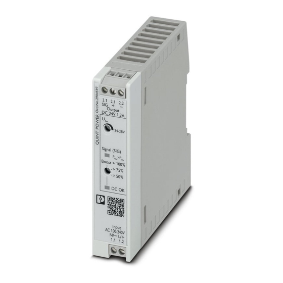
QUINT4-PS/12-24DC/24DC/1.3/SC
DC/DC converter
Data sheet
110257_en_00
1
Description
QUINT POWER power supplies are exceptionally small yet
offer superior system availability in the sub 100 W power
range.
Powerful
–
Static boost of up to 125% (P
–
Dynamic boost of up to 200% (P
Space-saving
–
Slim design
–
Slim design for 120 mm control boxes
Preventive
–
Function monitoring through adjustable signaling of
power thresholds or output voltage
Flexible connection technology
–
Tried-and-tested screw connection
–
Fast Push-in connection
Durable
–
Efficiency up to 92%
–
Low power dissipation
All technical specifications are nominal and refer to a room temperature of 25 °C and 70% relative humidity at
100 m above sea level.
© PHOENIX CONTACT
) for a sustained period
N
) for 4.9 s
N
2021-07-21
Technical data (short form)
Input voltage range
Mains buffering
Nominal output voltage (U
)
N
Setting range of the output voltage
(U
)
Set
Nominal output current (I
)
N
Static Boost (I
)
Stat.Boost
Dynamic Boost (I
)
Dyn.Boost
Output power (P
)
N
Output power (P
)
Stat. Boost
Output power (P
)
Dyn. Boost
Efficiency
Residual ripple
MTBF (IEC 61709, SN 29500)
Ambient temperature (operation)
Dimensions W/H/D
Weight
12 V DC ... 24 V DC -25 % ... +33 %
typ. 19 ms (24 V DC)
24 V DC
24 V DC ... 28 V DC
1.3 A
1.625 A (≤ 40 °C)
2.6 A (≤ 60 °C (4,9 s))
30 W
38 W
60 W
typ. 91.7 % (24 V DC)
< 20 mV
PP
> 1120490 h (40 °C)
-25 °C ... 70 °C
-40°C (startup type tested)
> 60 °C Derating: 2.5 %/K
22.5 mm / 99 mm / 90 mm
0.171 kg
Advertisement
Table of Contents

Related Manuals for Phoenix Contact QUINT4-PS/12-24DC/24DC/1.3/SC


Summary of Contents for Phoenix Contact QUINT4-PS/12-24DC/24DC/1.3/SC
-
Page 1: Description
QUINT4-PS/12-24DC/24DC/1.3/SC DC/DC converter Data sheet 110257_en_00 © PHOENIX CONTACT 2021-07-21 Description QUINT POWER power supplies are exceptionally small yet offer superior system availability in the sub 100 W power Technical data (short form) range. Input voltage range 12 V DC ... 24 V DC -25 % ... +33 % Mains buffering typ. -
Page 2: Table Of Contents
QUINT4-PS/12-24DC/24DC/1.3/SC Table of contents Description ..........................1 Table of contents ........................2 Ordering data .......................... 3 Technical data ......................... 4 Safety and installation notes ....................14 High-voltage test (HIPOT) ..................... 15 Structure of the power supply ....................17 Mounting/removing the power supply ..................20 Device connection terminal blocks .................. -
Page 3: Ordering Data
QUINT4-PS/12-24DC/24DC/1.3/SC Ordering data Description Type Order No. Pcs./Pkt. Primary-switched DC/DC converter, QUINT POWER, DIN QUINT4-PS/12-24DC/24DC/ 1066703 rail mounting, Screw connection, input: 12 V DC - 24 1.3/SC V DC, output: 24 V DC / 1.3 A Accessories Type Order No. Pcs./Pkt. Screwdriver, flat bladed, size: 0.4 x 2.0 x 60 mm, 2-... -
Page 4: Technical Data
QUINT4-PS/12-24DC/24DC/1.3/SC Technical data Input data Unless otherwise stated, all data applies for 25°C ambient temperature, 230 V AC input voltage, and nominal output current (I Input voltage range 12 V DC ... 24 V DC -25 % ... +33 % Electric strength, max. 35 V DC (60 s) Current draw typ. - Page 5 QUINT4-PS/12-24DC/24DC/1.3/SC Electric strength of the insulation Housing Input Signaling Output Type test ( IEC/EN 61010-1 ) 2.6 kV DC Production test 1.3 kV DC Input current vs. output current 12 V DC/U : 24 V DC 24 V DC/U : 24 V DC...
- Page 6 QUINT4-PS/12-24DC/24DC/1.3/SC Output data Nominal output voltage (U 24 V DC Setting range of the output voltage (U ) ( > 24 V DC, 24 V DC ... 28 V DC constant capacity ) Nominal output current (I 1.3 A Static Boost (I 1.625 A (≤ 40 °C) Stat.Boost...
- Page 7 QUINT4-PS/12-24DC/24DC/1.3/SC Signal connection data Connection method Screw connection Conductor cross section, rigid 0.14 mm² ... 2.5 mm² Conductor cross section, flexible 0.14 mm² ... 2.5 mm² Conductor cross section flexible, with ferrule with plastic 0.25 mm² ... 2.5 mm² sleeve Conductor cross section flexible, with ferrule without 0.25 mm²...
- Page 8 QUINT4-PS/12-24DC/24DC/1.3/SC Efficiency 24 V DC typ. 91.7 % 12 V DC/U : 24 V DC 24 V DC/U : 24 V DC 0,00 0,25 0,50 0,75 1,00 1,25 1,50 1,75 2,00 Ambient conditions Ambient temperature (operation) -25 °C ... 70 °C (> 60 °C Derating: 2.5 %/K) The ambient temperature (operation) refers to IEC 61010 surrounding air temperature.
- Page 9 QUINT4-PS/12-24DC/24DC/1.3/SC Approvals UL Listed UL 61010-1 CAN/CSA C22.2 No. 61010-1-12 UL Listed UL 61010-2-201 CAN/CSA C22.2 No. 61010-2-201:18 UL 121201 & CSA C22.2 No. 213-17 Class I, Division 2, Groups A, B, C, D T4 (Hazardous Location) CB Scheme IEC 61010-1 IEC 61010-2-201 Shipbuilding DNV GL Current approvals/permissions for the product can be found in the download area under phoenixcontact.net/products...
- Page 10 QUINT4-PS/12-24DC/24DC/1.3/SC Electromagnetic compatibility Conformance with EMC Directive 2014/30/EU Noise emission according to EN 61000-6-3 (residential and commercial) and EN 61000-6-4 (industrial) CE basic standard Minimum normative Higher requirements in requirements practice (covered) Conducted noise emission EN 55016 EN 61000-6-4 (Class A) EN 61000-6-3 (Class B)
- Page 11 QUINT4-PS/12-24DC/24DC/1.3/SC Immunity according to EN 61000-6-1 (residential), EN 61000-6-2 (industrial), and EN 61000-6-5 (power station equipment zone), IEC/EN 61850-3 (energy supply) CE basic standard Minimum normative Higher requirements in requirements of practice (covered) EN 61000-6-2 (CE) (immunity for industrial environments) Surge voltage load (surge) EN 61000-4-5...
- Page 12 QUINT4-PS/12-24DC/24DC/1.3/SC Additional basic standard EN 61000-6-5 (immunity in power station), IEC/EN 61850-3 (energy supply) Basic standard Minimum normative Higher requirements in requirements of practice (covered) EN 61000-6-5 Pulse-shape magnetic field EN 61000-4-9 not required 1000 A/m Comments none Criterion A Damped oscillating magnetic field EN 61000-4-10...
- Page 13 QUINT4-PS/12-24DC/24DC/1.3/SC Additional basic standard EN 61000-6-5 (immunity in power station), IEC/EN 61850-3 (energy supply) Basic standard Minimum normative Higher requirements in requirements of practice (covered) EN 61000-6-5 Voltage dips EN 61000-4-29 Input voltage ( 24 V DC ) Voltage dip 70 % , 100 ms ( Test Level 2 ) 70 % , 100 ms ( Test Level 2 )
-
Page 14: Safety And Installation Notes
QUINT4-PS/12-24DC/24DC/1.3/SC Safety and installation notes Safety notes and warning instructions Symbols used WARNING: Danger to life by electric shock! Instructions and possible hazards are indicated by corresponding symbols in this document. – Only skilled persons may install, start up, and operate This is the safety alert symbol. -
Page 15: High-Voltage Test (Hipot)
QUINT4-PS/12-24DC/24DC/1.3/SC High-voltage test (HIPOT) High-voltage dielectric test performed by the customer This protection class II power supply is subject to the Low Apart from routine and type tests to guarantee electrical Voltage Directive and is factory tested. During the HIPOT... - Page 16 QUINT4-PS/12-24DC/24DC/1.3/SC 6.3.1 Performing high-voltage testing If high-voltage testing of the control cabinet or the power supply as a stand-alone component is planned during final inspection and testing, the following features must be observed. – The power supply wiring must be implemented as shown in the wiring diagram.
-
Page 17: Structure Of The Power Supply
QUINT4-PS/12-24DC/24DC/1.3/SC Structure of the power supply Device dimensions Figure 3 Device dimensions (dimensions in mm) The fanless convection-cooled power supply can be snapped onto all DIN rails according to EN 60715. 22,5 Function elements Figure 2 Operating and indication elements 3.1 2.1 2.2 Output DC 3.1 2.1 2.2... - Page 18 QUINT4-PS/12-24DC/24DC/1.3/SC Keep-out areas Nominal output Spacing [mm] capacity < 50 % ≥ 50 % Figure 5 Device dimensions and minimum keep-out areas (in mm) 22,5 3.1 2.1 2.2 Output DC Signal (SIG) > P Boost >100% > 75% > 50%...
- Page 19 QUINT4-PS/12-24DC/24DC/1.3/SC Block diagram Figure 6 Block diagram Symbol Designation Symbol Designation Surge protection (diode) with filter Auxiliary converter (electrically isolating) Microcontroller Inrush current limitation PNP transistor switch output Switching transistor and main transmitter (electrically isolating) Rotary selector switch Secondary rectification and smoothing...
-
Page 20: Mounting/Removing The Power Supply
QUINT4-PS/12-24DC/24DC/1.3/SC Mounting/removing the power Removing the power supply unit supply Proceed as follows to remove the power supply: Take a suitable screwdriver and insert this into the lock Mounting the power supply unit hole on the integrated snap-on foot (A). - Page 21 QUINT4-PS/12-24DC/24DC/1.3/SC Fix connection wiring to the power supply – Shorten the excess length of the cable ties. – Then check again that the connection wiring is properly Two receptacles for the bundled attachment of the secured. connection wiring are integrated in the left and right housing panel.
-
Page 22: Device Connection Terminal Blocks
QUINT4-PS/12-24DC/24DC/1.3/SC Device connection terminal blocks Output characteristic curves The U/I output characteristic curve is optimized for the For the necessary connection parameters for the following applications: connection terminal blocks, refer to the technical – When supplying loads with high switch-on currents, data section. -
Page 23: Boost Currents
QUINT4-PS/12-24DC/24DC/1.3/SC Boost currents Use the following tables to determine the required recovery time (t ) at the maximum dynamic boost current (I Pause Dyn. The power supply provides the static boost (I ) for a ) based on the following values: Stat. - Page 24 QUINT4-PS/12-24DC/24DC/1.3/SC 11.2.3 Example: Determining the recovery time Pause At an output current (I ) of 0.65 A, the dynamic Base Load output current (I ) of 2.6 A increases for 2 s Dyn. Boost ). After a recovery time (t ) of 6 s, the dynamic...
-
Page 25: Signaling
QUINT4-PS/12-24DC/24DC/1.3/SC Signaling 12.3 Location and function of the signaling elements Figure 19 Position of signaling elements For signaling and the functional monitoring of the power supply two LEDs and an active signal output are available. Using the rotary selector select the required functional monitoring. - Page 26 "3.1 SIG" and "2.2 -" or 2.3 -". The maximum world. load is 30 mA. Use Phoenix Contact surge protection (Order No. 2905223) when you are using connection terminal blocks "3.1 SIG" Figure 21 Signaling and "2.2 -"...
-
Page 27: Operating Modes
QUINT4-PS/12-24DC/24DC/1.3/SC Operating modes 13.2 Parallel operation You can connect several power supplies in parallel in order Depending on the intended use, the power supply can be to increase the power or to supply the loads redundantly. run in series or parallel operation. - Page 28 QUINT4-PS/12-24DC/24DC/1.3/SC 13.2.1 Redundancy operation increased power is used when extending existing systems. If the individual power supply does not cover the current Redundant circuits are suitable for supplying systems and consumption of the most powerful load, parallel connection system parts which place particularly high demands on of power supplies is recommended.
-
Page 29: Derating
QUINT4-PS/12-24DC/24DC/1.3/SC Derating 14.2 Installation height The power supply can be operated at an installation height The QUINT POWER power supply runs in nominal of up to 2000 m without any limitations. Different data operation without any limitations. For operation outside the applies for installation locations above 2000 m due to the... - Page 30 QUINT4-PS/12-24DC/24DC/1.3/SC 14.3 Position-dependent derating The fanless convection-cooled power supply can be snapped onto all DIN rails according to EN 60715. The power supply should be mounted horizontally for heat dissipation reasons (input connection terminal blocks facing downward). Please observe the derating for any mounting other than the normal mounting position. Reduce the output power based on the prevailing ambient temperature.
- Page 31 QUINT4-PS/12-24DC/24DC/1.3/SC 14.3.3 Rotated mounting position 180° Z-axis 14.3.4 Rotated mounting position 270° Z-axis 110257_en_00 PHOENIX CONTACT 31/32...
- Page 32 QUINT4-PS/12-24DC/24DC/1.3/SC 14.3.5 Rotated mounting position 90° X-axis 14.3.6 Rotated mounting position 270° X-axis PHOENIX CONTACT GmbH & Co. KG • 32823 Blomberg • Germany 110257_en_00 32/32 phoenixcontact.com...
Need help?
Do you have a question about the QUINT4-PS/12-24DC/24DC/1.3/SC and is the answer not in the manual?
Questions and answers