Phoenix Contact GW PN/ASCII 1E/1DB9 User Manual
Protocol converter for ascii to profinet
Hide thumbs
Also See for GW PN/ASCII 1E/1DB9:
- User manual (90 pages) ,
- User manual (72 pages) ,
- User manual (34 pages)
Table of Contents
Advertisement
Quick Links
Advertisement
Chapters
Table of Contents

Related Manuals for Phoenix Contact GW PN/ASCII 1E/1DB9


Summary of Contents for Phoenix Contact GW PN/ASCII 1E/1DB9
- Page 1 Protocol converter for ASCII to ® PROFINET User manual...
-
Page 2: Gw Pn/Ascii 1E/1Db9
User manual ® Protocol converter for ASCII to PROFINET 2018-04-11 Revision: This user manual is valid for: Designation Order No. GW PN/ASCII 1E/1DB9 1021080 GW PN/ASCII 1E/2DB9 1021058 GW PN/ASCII 2E/2DB9 1021056 GW PN/ASCII 2E/4DB9 1020882 PHOENIX CONTACT 3886_en_A... -
Page 3: Table Of Contents
3.9.3 Serial logs .................... 33 3.9.4 Ethernet logs ..................34 3.10 Maintenance......................35 3.10.1 Passwords ................... 35 3.10.2 Restore defaults ................... 36 3.10.3 Log files ....................37 3.10.4 Configuration files ................38 3.10.5 Update firmware .................. 38 3886_en_A PHOENIX CONTACT... - Page 4 Data format of an output submodule............ 41 Troubleshooting........................43 Resetting the device .................... 43 5.1.1 Hardware reset ..................43 5.1.2 Software reset ..................43 LEDs........................43 Appendixes..........................45 List of figures ...................... 45 List of tables ....................... 47 PHOENIX CONTACT 3886_en_A...
-
Page 5: Description
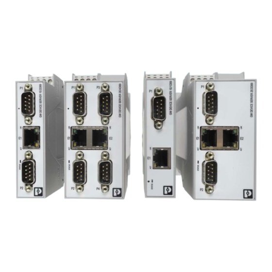
Ethernet ports to fit any application. This user manual is valid for: Table 1-1 GW PN/ASCII... types Type Description Order No. GW PN/ASCII 1E/1DB9 1021080 GW PN/ASCII 1E/2DB9 1021058 GW PN/ASCII 2E/2DB9 1021056 GW PN/ASCII 2E/4DB9... -
Page 6: Structure
GW PN/ASCII... Structure GW PN/ASCII 1E/1DB9 The GW PN/ASCII 1E/1DB9 features one Ethernet port and one RS-232/422/485 serial port with a D-SUB 9 connector. Figure 1-1 GW PN/ASCII 1E/1DB9 Table 1-2 GW PN/ASCII 1E/1DB9 structure Item Description Power connector P1 D-SUB 9 connector... -
Page 7: Gw Pn/Ascii 1E/2Db9
Figure 1-2 GW PN/ASCII 1E/2DB9 Table 1-3 GW PN/ASCII 1E/2DB9 structure Item Description Power connector P1 D-SUB 9 connector Ethernet port (RJ45) P2 D-SUB 9 connector Status LED Ethernet activity status LED Ethernet link status LED Reset button 3886_en_A PHOENIX CONTACT... -
Page 8: Gw Pn/Ascii 2E/2Db9
Power connector P1 D-SUB 9 connector Ethernet link status LED E2 Ethernet port (RJ45) Ethernet activity status LED P2 D-SUB 9 connector Status LED Ethernet activity status LED E1 Ethernet port (RJ45) Ethernet link status LED Reset button PHOENIX CONTACT 3886_en_A... -
Page 9: Gw Pn/Ascii 2E/4Db9
Ethernet link status LED E2 Ethernet port (RJ45) Ethernet activity status LED P4 D-SUB 9 connector P2 D-SUB 9 connector Status LED Ethernet activity status LED E1 Ethernet port (RJ45) Ethernet link status LED Reset button P1 D-SUB 9 connector 3886_en_A PHOENIX CONTACT... - Page 10 GW PN/ASCII... PHOENIX CONTACT 3886_en_A...
-
Page 11: Installation
Hold the device by the housing cover and carefully push the device toward the mounting surface (B). After the foot is snapped onto the DIN rail, verify that it is attached securely. Figure 2-1 DIN rail mounting 3886_en_A PHOENIX CONTACT... - Page 12 Use a suitable screwdriver to release the locking mechanism (A) on the snap-on foot of the device. Hold on to the device by the housing cover and carefully tilt it upward (B). Remove the device from the DIN rail (C). Figure 2-2 DIN rail removal PHOENIX CONTACT 3886_en_A...
-
Page 13: Data Interfaces
2799474). The cable is an interface cable with 1:1 connected contacts. Table 2-1 D-SUB 9 to RS-232 pin out GW PN/ASCII... End device RS-232 D-SUB 9 D-SUB 9 D-SUB 25 D-SUB 25 (DCE) (DTE) (DCE) (DTE) 1, 6 6, 8 3886_en_A PHOENIX CONTACT... -
Page 14: Connecting The Rs-422 Cable
Observe the polarity of the RS-485 cable. Fit this bus cable with a termination network at the two furthest points of the RS-485 network. The termination resistors are integrated in the GW PN/ASCII... and can be switched on through the web-based management interface. PHOENIX CONTACT 3886_en_A... -
Page 15: Connecting The Ethernet Cable
The maximum number of segments connected on a network is five. – Four repeaters is the maximum that can be applied to a network. – Only three segments can have user connections. The other two segments must act as repeaters with no user connections. 3886_en_A PHOENIX CONTACT... -
Page 16: Connecting The Power Supply
The GW PN/ASCII... is powered using a +24 V DC SELV power supply. The power supply is connected by way of COMBICON plug-in screw terminal blocks (24 V and 0 V). Figure 2-4 Single power supply connection Figure 2-5 Redundant power supply connection PHOENIX CONTACT 3886_en_A... -
Page 17: Configuration And Startup
If the web server does not load, first check the IP parameters of the PC. If everything is set correctly, check to see if there are any proxy settings loaded in the web browser. The proxy setting must be set to “Load automatically” or “Deactivated” to properly establish communication. 3886_en_A PHOENIX CONTACT... -
Page 18: Home Screen
Advanced settings can be accessed through the menu at the top of the screen. The “Home” screen can be accessed at any time by clicking the “Home” button in the upper-left corner of the web-based management interface. PHOENIX CONTACT 3886_en_A... -
Page 19: General Settings
Device Name: Enter a name for the device. The field accepts up to 16 characters. Contact: Enter the name of a contact person, group, or department responsible for this device. The field accepts up to 16 characters. Click the “Apply Changes” button to save the configuration. 3886_en_A PHOENIX CONTACT... -
Page 20: Lan Settings
MAC Address: The MAC address of the GW PN/ASCII... is displayed. Click the “Apply Changes” button to save the configuration. Discover and basic configuration protocol (DCP) settings will overwrite the Device Name configured in the web manager. PHOENIX CONTACT 3886_en_A... -
Page 21: Security
In order to function properly, this certificate must be signed using the RSA server key. This means that the RSA server certificate and RSA server key must be replaced as a pair. 3886_en_A PHOENIX CONTACT... -
Page 22: Profinet Io
“Diagnostics System Log” file. Items logged include Thread name, ID, State, Priority, Stacksize, Stackused, SuspendCnt, WakeupCnt, SleepReason, WakeReason, TimerID, Type, Base, Count, Callback, UserID, Message_Queue, TaskID, Length, MaxLen, Sent, Received, and Error. PHOENIX CONTACT 3886_en_A... -
Page 23: Serial Settings
The “Overview” page provides a quick summary of the current configuration of the serial port(s). Click the appropriate configuration tab to edit the configuration of that port. Figure 3-7 “Serial Settings/Overview” page 3.7.1 Port configuration Figure 3-8 “Serial Settings/Port 1 Configuration/Serial Port Configuration” page 3886_en_A PHOENIX CONTACT... -
Page 24: Serial Port Configuration" Dialog Box
IO controller as cyclic IO data. When SaveRec is enabled, oversized packets are truncated and sent to the IO controller as cyclic IO data while saving the original packets as acyclic record data. When Drop is enabled, oversized packets are dropped. PHOENIX CONTACT 3886_en_A... -
Page 25: Raw/Ascii Serial Packet Delimiiters" Dialog Box
GW PN/ASCII... are not checked for STX/ETX characters. The GW PN/ASCII... modules can also be configured to append characters to the beginning or end of a serial packet. Similar information is then entered under “Append Delimiters from PLC” in the same group: 3886_en_A PHOENIX CONTACT... - Page 26 FF in hexadecimal format. – Byte 2: Specifies the character that represents the second ETX byte. The GW PN/ASCII... adds this byte only if the length is two bytes. Specify a value between 0 and FF in hexadecimal format. PHOENIX CONTACT 3886_en_A...
-
Page 27: Socket Settings
“Socket Configuration” tab. The number of Ethernet TCP/IP connections supported by the GW PN/ASCII... is equal to the number of Ethernet ports on the device, but the TCP/IP connections are not directly linked to a particular serial port. 3886_en_A PHOENIX CONTACT... -
Page 28: Socket Configuration
Listen: Check the “Listen” box so that the GW PN/ASCII... listens for incoming TCP/IP socket connections on the port number specified in the “On port” field. – On port: Enter the TCP port number on which the GW PN/ASCII... listens for connections. PHOENIX CONTACT 3886_en_A... - Page 29 Byte 1: Specifies the character that represents the first ETX byte. The GW PN/ASCII... looks for this character in the first ETX byte, if the length is one byte or two bytes. Specify a value between 0 and FF in hexadecimal format. 3886_en_A PHOENIX CONTACT...
- Page 30 FF in hexadecimal format. – Byte 2: Specifies the character that represents the second ETX byte. The GW PN/ASCII... adds this byte only if the length is two bytes. Specify a value between 0 and FF in hexadecimal format. PHOENIX CONTACT 3886_en_A...
-
Page 31: Diagnostics
RX packet count: This displays the number of packets received on the serial port. Parity error count: This displays the number of parity errors dropped due to parity errors. Framing error count: This displays the number of received serial packets dropped due to framing errors. 3886_en_A PHOENIX CONTACT... - Page 32 To PLC packet count: This displays the number of Ethernet packets sent to the PLC. To PLC dropped packet count: This displays the number of Ethernet packets intended for the PLC that were dropped. Packets are dropped in the following circumstances: PHOENIX CONTACT 3886_en_A...
-
Page 33: Plc Interface
Application relationship 1 uptime: This displays the uptime of application relationship 1. Application relationship 2 uptime: This displays the uptime of application relationship 2. Total application relationships: This displays the total number of application relationships that have been established. 3886_en_A PHOENIX CONTACT... - Page 34 Idle count (min / current / max): This displays the minimum, current, and maximum CPU idle count of the GW PN/ASCII..Idle count history (1 / 5 / 15 mins): This displays the average CPU idle count in the last 1, 5, and 15 minutes. PHOENIX CONTACT 3886_en_A...
-
Page 35: Serial Logs
(data): Data packet received. For PROFINET IO data, all data bytes are shown in hexadecimal (xxh) format. For Raw/ASCII and PROFINET/ASCII data, ASCII characters are displayed as characters. Non-ASCII data is displayed in hexadecimal (xxh) format Click the “Reset Log” button to clear the log. 3886_en_A PHOENIX CONTACT... -
Page 36: Ethernet Logs
<data> - Data packet received. For PROFINET IO data, all data bytes are shown in hexadecimal (xxh) format. For Raw/ASCII and PROFINET/ASCII data, ASCII characters are displayed as characters. Non-ASCII data is displayed in hexadecimal (xxh) format PHOENIX CONTACT 3886_en_A... -
Page 37: Maintenance
Password: admin The “Password” field is case sensitive. The user name is fixed and cannot be modified. Enter the current password and the new password (twice) in the appropriate fields. Click the “Apply Changes” button to save changes. 3886_en_A PHOENIX CONTACT... -
Page 38: Restore Defaults
Check the “Check the box to confirm...” box. Click the “Apply Changes” button. Note that the IP address returns to the factory defaults and may require modification to prevent multiple devices on the network from trying to use the same address. PHOENIX CONTACT 3886_en_A... -
Page 39: Log Files
GW PN/ASCII..The “Device Snapshot” feature allows a user to capture the system log, configuration data, and other information that can be used for advanced troubleshooting or for “As Configured” record keeping as a single text file. 3886_en_A PHOENIX CONTACT... -
Page 40: Configuration Files
After selecting the appropriate configuration file, enter the password for the file and click the “Load Configuration” button. 3.10.5 Update firmware To update firmware: From the “Device Maintenance” page, click the “Update Firmware” tab to install a new version of the firmware. Figure 3-22 “Update Firmware” page PHOENIX CONTACT 3886_en_A... - Page 41 Click the “Apply Changes” button to install the firmware. NOTE: Ensure that a reliable power connection is available during the firmware update. Do not restart the module or disconnect the Ethernet cable during this process. When firmware is updated, the device configuration is maintained. 3886_en_A PHOENIX CONTACT...
- Page 42 GW PN/ASCII... PHOENIX CONTACT 3886_en_A...
- Page 43 GW PN/ASCII... transmits the number of output data indicated by the length field when the sequence number field changes. The GW PN/ASCII... only transmits the output data once. No further data is transmitted until the sequence number is changed again. 3886_en_A PHOENIX CONTACT...
- Page 44 If they are the same, the data has been transmitted successfully. Table 4-4 Byte offset Byte Offset Data Type Description WORD Last Transmitted Sequence Number (Big endian) PHOENIX CONTACT 3886_en_A...
- Page 45 3 flashes per 5 Indicates an internal error seconds LINK Green On solid Indicates Ethernet network is connected Yellow Flashing Flashing indicates data transfer activity LEDs on Ethernet ports are not labeled. See Section 1.1, “Structure” for LED location. 3886_en_A PHOENIX CONTACT...
- Page 46 GW PN/ASCII... PHOENIX CONTACT 3886_en_A...
- Page 47 A Appendixes List of figures Section 1 Figure 1-1: GW PN/ASCII 1E/1DB9 ............... 4 Figure 1-2: GW PN/ASCII 1E/2DB9 ................ 5 Figure 1-3: GW PN/ASCII 2E/2DB9 ................ 6 Figure 1-4: GW PN/ASCII 2E/4DB9 ............... 7 Section 2 Figure 2-1: DIN rail mounting .................. 9 Figure 2-2: DIN rail removal ..................
- Page 48 GW PN/ASCII... Figure 3-18: “Password” page ................35 Figure 3-19: “Restore Defaults” page ..............36 Figure 3-20: “Log Files” page .................. 37 Figure 3-21: “Config Files” page ................38 Figure 3-22: “Update Firmware” page ..............38 PHOENIX CONTACT 3886_en_A...
- Page 49 List of tables Section 1 Table 1-1: GW PN/ASCII... types................3 Table 1-2: GW PN/ASCII 1E/1DB9 structure ............4 Table 1-3: GW PN/ASCII 1E/2DB9 structure ............5 Table 1-4: GW PN/ASCII 2E/2DB9 structure ............6 Table 1-5: GW PN/ASCII 2E/4DB9 structure ............7...
- Page 50 GW PN/ASCII... PHOENIX CONTACT 3886_en_A...
- Page 51 The receipt of technical documentation (in particular user documentation) does not constitute any further duty on the part of Phoenix Contact to furnish information on modifications to products and/or technical documentation. You are responsible to verify the suitability and intended use of the products in your specific application, in particular with regard to observing the applicable standards and regulations.
- Page 52 Middletown, PA 17057 Should you have any suggestions or recommendations for improvement of the contents and layout of our manuals, please send your comments to: tecdoc@phoenixcontact.com PHOENIX CONTACT GmbH & Co. KG • Flachsmarktstraße 8 • 32825 Blomberg • Germany phoenixcontact.com...
Need help?
Do you have a question about the GW PN/ASCII 1E/1DB9 and is the answer not in the manual?
Questions and answers