Phoenix Contact GW EIP/ASCII 1E/1DB9 User Manual
Protocol converter for ascii to ethernet/ip
Hide thumbs
Also See for GW EIP/ASCII 1E/1DB9:
- User manual (72 pages) ,
- User manual (34 pages) ,
- User manual (52 pages)
Table of Contents
Advertisement
Quick Links
Advertisement
Chapters
Table of Contents
Troubleshooting

Related Manuals for Phoenix Contact GW EIP/ASCII 1E/1DB9


Summary of Contents for Phoenix Contact GW EIP/ASCII 1E/1DB9
- Page 1 Protocol converter for ASCII to EtherNet/IP™ User manual UM EN GW EIP/ASCII...
-
Page 2: Gw Eip/Ascii 1E/1Db9
This user manual is valid for: Designation Order No. GW EIP/ASCII 1E/1DB9 2702772 GW EIP/ASCII 1E/2DB9 2702773 GW EIP/ASCII 2E/2DB9 2702774 GW EIP/ASCII 2E/4DB9 2702776 PHOENIX CONTACT GmbH & Co. KG • Flachsmarktstraße 8 • 32825 Blomberg • Germany phoenixcontact.com... -
Page 3: Table Of Contents
4.6.2 Security ....................23 4.6.3 EtherNet/IP stack ................. 24 Serial settings ...................... 25 4.7.1 Port configuration ................. 26 4.7.2 EtherNet/IP configuration ..............29 Socket settings ....................32 4.8.1 Socket settings ..................33 4.8.2 EtherNet/IP configuration ..............35 3785_en_B PHOENIX CONTACT... - Page 4 Received message characteristics ............76 Transmit data message ..................77 6.5.1 Transmit message characteristics ............77 Sequence number messages................77 Receive communication methods................ 78 6.7.1 Write to Tag/File - Unsolicited message ..........78 6.7.2 Polling ....................78 PHOENIX CONTACT 3785_en_B...
- Page 5 Software reset ..................79 LEDs........................79 EDS files ...........................81 Add the GW EIP/ASCII... to RSLinx..............81 Add the EDS file to RSLinx .................. 81 Troubleshooting RSLinx ..................82 Appendixes..........................83 List of figures ...................... 83 List of tables ....................... 85 3785_en_B PHOENIX CONTACT...
- Page 6 GW EIP/ASCII... PHOENIX CONTACT 3785_en_B...
-
Page 7: For Your Safety
The Radioline wireless system is a Class A item of equipment and may cause radio interference in residential areas. In this case, the operator may be required to implement appropriate measures and to pay the costs incurred as a result. 3785_en_B PHOENIX CONTACT... -
Page 8: Product Changes
Changes or modifications to hardware and software of the device are not permitted. Incorrect operation or modifications to the device can endanger your safety or damage the device. Do not repair the device yourself. If the device is defective, please contact Phoenix Contact. Precautionary statements for use in hazardous lo- cations WARNING: The following is specified by the approving test lab. -
Page 9: Description
Ethernet ports to fit any application. This user manual is valid for: Table 2-1 GW EIP/ASCII... types Type Description Order No. GW EIP/ASCII 1E/1DB9 2702772 GW EIP/ASCII 1E/2DB9 2702773 GW EIP/ASCII 2E/2DB9 2702774 GW EIP/ASCII 2E/4DB9... -
Page 10: Structure
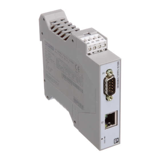
GW EIP/ASCII... Structure GW EIP/ASCII 1E/1DB9 The GW EIP/ASCII 1E/1DB9 features one Ethernet port and one RS-232/422/485 serial port with a D-SUB 9 connector. Figure 2-1 GW EIP/ASCII 1E/1DB9 Table 2-2 GW EIP/ASCII 1E/1DB9 structure Item Description Power connector P1 D-SUB 9 connector... -
Page 11: Gw Eip/Ascii 1E/2Db9
Figure 2-2 GW EIP/ASCII 1E/2DB9 Table 2-3 GW EIP/ASCII 1E/2DB9 structure Item Description Power connector P1 D-SUB 9 connector Ethernet port (RJ45) P2 D-SUB 9 connector Status LED Ethernet activity status LED Ethernet link status LED Reset button 3785_en_B PHOENIX CONTACT... -
Page 12: Gw Eip/Ascii 2E/2Db9
Power connector P1 D-SUB 9 connector Ethernet link status LED E2 Ethernet port (RJ45) Ethernet activity status LED P2 D-SUB 9 connector Status LED Ethernet activity status LED E1 Ethernet port (RJ45) Ethernet link status LED Reset button PHOENIX CONTACT 3785_en_B... -
Page 13: Gw Eip/Ascii 2E/4Db9
Ethernet link status LED E2 Ethernet port (RJ45) Ethernet activity status LED P4 D-SUB 9 connector P2 D-SUB 9 connector Status LED Ethernet activity status LED E1 Ethernet port (RJ45) Ethernet link status LED Reset button P1 D-SUB 9 connector 3785_en_B PHOENIX CONTACT... - Page 14 GW EIP/ASCII... PHOENIX CONTACT 3785_en_B...
-
Page 15: Installation
Hold the device by the housing cover and carefully push the device toward the mounting surface (B). After the foot is snapped onto the DIN rail, verify that it is attached securely. Figure 3-1 DIN rail mounting 3785_en_B PHOENIX CONTACT... - Page 16 Use a suitable screwdriver to release the locking mechanism (A) on the snap-on foot of the device. Hold on to the device by the housing cover and carefully tilt it upward (B). Remove the device from the DIN rail (C). Figure 3-2 DIN rail removal PHOENIX CONTACT 3785_en_B...
-
Page 17: Data Interfaces
2799474). The cable is an interface cable with 1:1 connected contacts. Table 3-1 D-SUB 9 to RS-232 pin out GW EIP/ASCII... End device RS-232 D-SUB 9 D-SUB 9 D-SUB 25 D-SUB 25 (DCE) (DTE) (DCE) (DTE) 1, 6 6, 8 3785_en_B PHOENIX CONTACT... -
Page 18: Connecting The Rs-422 Cable
Observe the polarity of the RS-485 cable. Fit this bus cable with a termination network at the two furthest points of the RS-485 network. The termination resistors are integrated in the GW EIP/ASCII... and can be switched on through the web-based management interface. PHOENIX CONTACT 3785_en_B... -
Page 19: Connecting The Ethernet Cable
The maximum number of segments connected on a network is five. – Four repeaters is the maximum that can be applied to a network. – Only three segments can have user connections. The other two segments must act as repeaters with no user connections. 3785_en_B PHOENIX CONTACT... -
Page 20: Connecting The Power Supply
The GW EIP/ASCII... is powered using a +24 V DC SELV power supply. The power supply is connected by way of COMBICON plug-in screw terminal blocks (24 V and 0 V). Figure 3-4 Single power supply connection Figure 3-5 Redundant power supply connection PHOENIX CONTACT 3785_en_B... -
Page 21: Configuration And Startup
If the web server does not load, first check the IP parameters of the PC. If everything is set correctly, check to see if there are any proxy settings loaded in the web browser. The proxy setting must be set to “Load automatically” or “Deactivated” to properly establish communication. 3785_en_B PHOENIX CONTACT... -
Page 22: Home Screen
Advanced settings can be accessed through the menu at the top of the screen. The “Home” screen can be accessed at any time by clicking the “Home” button in the upper-left corner of the web-based management interface. PHOENIX CONTACT 3785_en_B... -
Page 23: General Settings
Device Name: Enter a name for the device. The field accepts up to 16 characters. Contact: Enter the name of a contact person, group, or department responsible for this device. The field accepts up to 16 characters. Click the “Apply Changes” button to save the configuration. 3785_en_B PHOENIX CONTACT... -
Page 24: Lan Settings
If using static IP addresses, click the “Manual address assignment” button and enter the appropriate information in the various fields. MAC Address: The MAC address of the GW EIP/ASCII... is displayed. Click the “Apply Changes” button to save the configuration. PHOENIX CONTACT 3785_en_B... -
Page 25: Security
SSL client if requested by the server. In order to function properly, this certificate must be signed using the RSA server key. This means that the RSA server certificate and RSA server key must be replaced as a pair. 3785_en_B PHOENIX CONTACT... -
Page 26: Ethernet/Ip Stack
User Defined, the GW EIP/ASCII... begins its multicast IP address range at the value entered. Session encapsulation timeout: The GW EIP/ASCII... waits the designated time in seconds with no activity before timing out a session. A value of 0 disables the timeout functionality. PHOENIX CONTACT 3785_en_B... -
Page 27: Serial Settings
Click the “Serial Settings” tab to configure the serial port(s). The “Overview” page provides a quick summary of the current configuration of the serial port(s). Click the appropriate configuration tab to edit the configuration of that port. Figure 4-7 “Serial Settings/Overview” page 3785_en_B PHOENIX CONTACT... -
Page 28: Port Configuration
Baud rate: Select the baud rate of the serial port; 300, 600, 1200, 2400, 4800, 9600, 19200, 38400, 57600, 115200, and 230400 bps are supported. Parity: Select odd, even, mark, space, or none. Data bits: Select 5, 6, 7, or 8 data bits. PHOENIX CONTACT 3785_en_B... -
Page 29: Raw/Ascii Serial Packet Delimiiters" Dialog Box
If one byte is selected, the serial data is checked for one ETX byte to identify the end of a serial packet. If two bytes is selected, the serial data is checked for two ETX bytes to identify the end of a serial packet. 3785_en_B PHOENIX CONTACT... - Page 30 FF in hexadecimal format. – Byte 2: Specifies the character that represents the second ETX byte. The GW EIP/ASCII... adds this byte only if the length is two bytes. Specify a value between 0 and FF in decimal format. PHOENIX CONTACT 3785_en_B...
-
Page 31: Ethernet/Ip Configuration
However, it does require periodic data requests and the request rate must be fast enough to ensure that the serial port RX queues on the GW EIP/ASCII... do not overflow. The default is Class 1. 3785_en_B PHOENIX CONTACT... - Page 32 40 characters. The “Tag/file” name must be a global variable in the PLC. Enter the tag/file name exactly as it is in the PLC. A MicroLogix type file name must be N10 or greater and have the format N10:0. The Polling method does not use this attribute. PHOENIX CONTACT 3785_en_B...
-
Page 33: Class 1 Overview" Page
(LSB) is transmitted first. 4.7.2.1 Class 1 overview The “Class 1 Overview” pages provide an array of highly informative Class 1 interface information to aid when programming a PLC. Figure 4-12 “Class 1 Overview” page 3785_en_B PHOENIX CONTACT... -
Page 34: Socket Settings
“Socket Configuration” tab. The number of Ethernet TCP/IP connections supported by the GW EIP/ASCII... is equal to the number of serial ports on the device, but the TCP/IP connections are not directly linked to a particular serial port. PHOENIX CONTACT 3785_en_B... -
Page 35: Socket Settings
Connect to IP address: Enter an IP address to which the GW EIP/ASCII... initiates a – connection. Use the standard AAA.BBB.CCC.DDD format. Connect to port: Enter a TCP Port number to which the GW EIP/ASCII... initiates a – connection. 3785_en_B PHOENIX CONTACT... - Page 36 Packets sent from the PLC by way of Ethernet to the serial ports of the GW EIP/ASCII... are not checked for STX/ETX characters. The GW EIP/ASCII... modules can also be configured to append characters to the beginning or end of a serial packet. PHOENIX CONTACT 3785_en_B...
-
Page 37: Ethernet/Ip Configuration
PLC type: The GW EIP/ASCII... provides EtherNet/IP connectivity to the entire ControlLogix family of PLCs as well as the SLC, PLC-5, and MicroLogix PLCs. The ControlLogix setting supports full CIP interfaces including Class 1, Write to Tag and full 3785_en_B PHOENIX CONTACT... - Page 38 Maximum RX packet size: When Write to Tag/File or Polling in the “Transfer mode to PLC” field are selected, this setting specifies the maximum acceptable size of a received serial or Ethernet packet. The default value is 2048 bytes for serial ports. When Class 1 in PHOENIX CONTACT 3785_en_B...
- Page 39 Transmit MicroLogix MSB first: Enable this option when the GW EIP/ASCII... should transmit the most significant byte (MSB) of a 16-bit integer first. This option is disabled by default and the least significant byte (LSB) is transmitted first. 3785_en_B PHOENIX CONTACT...
-
Page 40: Figure 4-17 "Class 1 Overview" Page
GW EIP/ASCII... 4.8.2.1 Class 1 overview The “Class 1 Overview” pages provide an array of highly informative Class 1 interface information to aid when programming a PLC. Figure 4-17 “Class 1 Overview” page PHOENIX CONTACT 3785_en_B... -
Page 41: Diagnostics
To PLC dropped packet count: The number of received serial packets that were intended for the PLC but were dropped due to any of the following conditions: no STX byte(s) found, no ETX byte(s) found, a timeout occurred, the packet was too large, or the receive buffer queue overflowed. 3785_en_B PHOENIX CONTACT... - Page 42 It is expected that the sequence number is incremented for each transmit message. If desired, click the “Reset Statistics” button to refresh the statistics shown. PHOENIX CONTACT 3785_en_B...
-
Page 43: Plc Interface
Class 1 output updates from PLC: Displays the number of Class 1 output data updates received from the PLCs. Class 1 input updates to PLC: Displays the number of Class 1 input data updates sent to the PLCs. 3785_en_B PHOENIX CONTACT... - Page 44 PLCs are sending data to the GW EIP/ASCII... at a faster rate than the GW EIP/ASCII... can process it. Oversized received data packet errors: The number of received serial or Ethernet data packets that were larger than the configured maximum receive data packet. PHOENIX CONTACT 3785_en_B...
-
Page 45: Serial Logs
(data): Raw/ASCII message data Click the “Reset Log” button to clear the log. 3785_en_B PHOENIX CONTACT... -
Page 46: Ethernet Logs
<data> - Data packet received. For EtherNet/IP slave data, all data bytes are shown in hexadecimal (xxh) format. For Raw/ASCII and EtherNet/IP/ASCII data, ASCII characters are displayed as characters. Non-ASCII data is displayed in hexadecimal (xxh) format PHOENIX CONTACT 3785_en_B... -
Page 47: Maintenance
Password: admin The “Password” field is case sensitive. The user name is fixed and cannot be modified. Enter the current password and the new password (twice) in the appropriate fields. Click the “Apply Changes” button to save changes. 3785_en_B PHOENIX CONTACT... -
Page 48: Restore Defaults
Check the “Check the box to confirm...” box. Click the “Apply Changes” button. Note that the IP address returns to the factory defaults and may require modification to prevent multiple devices on the network from trying to use the same address. PHOENIX CONTACT 3785_en_B... -
Page 49: Log Files
GW EIP/ASCII..The “Device Snapshot” feature allows a user to capture the system log, configuration data, and other information that can be used for advanced troubleshooting or for “As Configured” record keeping as a single text file. 3785_en_B PHOENIX CONTACT... -
Page 50: Configuration Files
After selecting the appropriate configuration file, enter the password for the file and click the “Load Configuration” button. 4.10.5 Update firmware To update firmware: From the “Device Maintenance” page, click the “Update Firmware” tab to install a new version of the firmware. Figure 4-26 “Update Firmware” page PHOENIX CONTACT 3785_en_B... - Page 51 Click the “Apply Changes” button to install the firmware. NOTE: Ensure that a reliable power connection is available during the firmware update. Do not restart the module or disconnect the Ethernet cable during this process. When firmware is updated, the device configuration is maintained. 3785_en_B PHOENIX CONTACT...
- Page 52 GW EIP/ASCII... PHOENIX CONTACT 3785_en_B...
-
Page 53: Data Message Format
Transmit message data (PLC to GW EIP/ASCII...) Name Data type Data value Access rule Produced data UINT 0-65535 (FFFF Read/Write sequence number Data length (in UINT 0-(MSG payload-4) Read/Write bytes) Data array Array of SINT 0-255 Read/Write 3785_en_B PHOENIX CONTACT... -
Page 54: Ethernet/Ip Interface Profile (Controllogix)
Serial port data transfer object class attributes Attribute ID Name Data type Data value Access rule Revision UINT Max instance UINT Number of ports on the GW EIP/ASCII... Num instances UINT Number of ports on the GW EIP/ASCII... PHOENIX CONTACT 3785_en_B... -
Page 55: Serial Port Data Transfer Object Instance Attributes
The maximum sized serial port message in the “Write-to-Tag” field when set to Transfer to PLC is 1518 bytes. Table 5-5 Serial port data transfer object common services Service code Implemented in Implemented in Service name class instance Get_Attribute_Single Set_Attribute_Single 3785_en_B PHOENIX CONTACT... -
Page 56: Serial Port Data Transfer Object Instance Attribute Definitions
Attribute 4: Transmit (PLC to This attribute gets and sets the “Transmit Produced Data Sequence” number. GW EIP/ASCII...) Produced Data This is the same “Produced Data Sequence” number sent to the Sequence Number GW EIP/ASCII... in the Transmit Message data. PHOENIX CONTACT 3785_en_B... -
Page 57: Socket Port Data Transfer Definition Object
PLC from the GW EIP/ASCII... in data transfer Transmit (PLC to GW EIP/ASCII...) produced data sequence number Normally sent to the UINT 0-65535 (FFFF Set/Get GW EIP/ASCII... from the PLC in data For polling transfer to PLC mode only 3785_en_B PHOENIX CONTACT... -
Page 58: Socket Port Data Transfer Object Common Services
Attribute 4: Transmit (PLC to This attribute gets and sets the “Transmit Produced Data Sequence” number. GW EIP/ASCII...) Produced Data This is the same “Produced Data Sequence” number sent to the Sequence Number GW EIP/ASCII... in the Transmit Message data. PHOENIX CONTACT 3785_en_B... -
Page 59: Informational Objects
Vendor ID UINT 562 (Phoenix Contact) Device type UINT 43 (Generic product device) Product code UINT As defined by Phoenix Contact Revision (product or software release) Structure of: Major revision USINT 1 - 127 Minor revision USINT 1 - 127... -
Page 60: Status Word
GW EIP/ASCII... may be required. No major unrecoverable fault A major unrecoverable fault has occurred in the GW EIP/ASCII..If the major fault is not corrected with a system reset or a power cycle, contact Phoenix Contact. 12-15 Reserved PHOENIX CONTACT 3785_en_B... -
Page 61: Message Router Object
Number of supported class codes Classes Array of UINT List of supported class codes Max connections UINT Table 5-17 Message router object common services Service code Implemented in Implemented in Service name class instance Get_Attribute_All Get_Attribute_Single Multiple_Service_Req 3785_en_B PHOENIX CONTACT... -
Page 62: Connection Manager Object
Close other requests UINT 0 - 0xFFFFFFFF Set/Get Connection timeouts UINT 0 - 0xFFFFFFFF Set/Get Table 5-20 Connection manager object common services (06 Service code Implemented in Implemented in Service name class instance Get_Attribute_All Set_Attribute_All Get_Attribute_Single Set_Attribute_Single Forward_Close Unconnected_Send PHOENIX CONTACT 3785_en_B... -
Page 63: Port Object
Maximum number UINT instance attributes Entry port UINT All ports Array of UINT [0] = 0 [1] = 0 [2] = 1 (vendor specific) [3] = 1 (backplane) [4] = TCP_IP_PORT_TYPE (4) [5] = TCP_IP_PORT_NUMBER (2) 3785_en_B PHOENIX CONTACT... -
Page 64: Table 5-23 Port Object Common Services
Bit 2: Routing of incoming Transport Class 0/1 Connections supported Bit 4: Routing of incoming Transport Class 2/3 Connections supported Table 5-23 Port object common services Service code Implemented in Implemented in Service name class instance Get_Attribute_All Get_Attribute_Single PHOENIX CONTACT 3785_en_B... -
Page 65: Tcp/Ip Object
Configuration control DWORD 0 = Use stored IP address (static IP address) 2 = DHCP Physical link object Structure of: Path size UINT Path Array of USINT [0] = 20 [1] = F6 [2] = 24 [3] = 01 3785_en_B PHOENIX CONTACT... -
Page 66: Table 5-26 Tcp/Ip Object Common Services
Encapsulation USINT Number of seconds of inactivity before TCP inactivity timeout connection or the DTLS session is closed Table 5-26 TCP/IP object common services Service code Implemented in Implemented in Service name class instance Get_Attribute_All Get_Attribute_Single Set_Attribute_Single PHOENIX CONTACT 3785_en_B... -
Page 67: Ethernet Link Object
Bit 1 = Half/full duplex (0 = half duplex, 2 = full status) duplex) Bits 2 - 4: 00 = Negotiation in progress 01 = Negotiation failed 02 = Negotiation failed, speed OK 03 = Negotiation success Physical address Array of 6 MAC address USINT 3785_en_B PHOENIX CONTACT... -
Page 68: Table 5-29: Ethernet Link Object Common Services
Capability bits - Interface capabilities; other than speed/duplex Value = 6 Bit 1: Autonegotiate Bit 2: Auto-MDIX USINT Speed/Duplex array count = 0 Table 5-29 Ethernet Link object common services Service code Implemented in Implemented in Service name class instance Get_Attribute_All Get_Attribute_Single PHOENIX CONTACT 3785_en_B... -
Page 69: Pccc Object
Serial Number UDINT ASA serial number of requester USINT Command byte USINT Status byte TNSW UINT Transport word - Same value as request. EXT_STS USINT Extended status (if error) PCCC_params Array of USINT CMD/FMC specific result data 3785_en_B PHOENIX CONTACT... -
Page 70: Assembly Object (For Class 1 Interface)
116 = Four-port models (GW EIP/ASCII.../4DB9) Num instance UINT 4 = One-port models (GW EIP/ASCII.../1DB9) 8 = Two-port models (GW EIP/ASCII.../2DB9) 16 = Four-port models (GW EIP/ASCII.../4DB9) Optional attribute list UINT Maximum number UINT class attribute Maximum number UINT instance attribute PHOENIX CONTACT 3785_en_B... -
Page 71: Table 5-35 Assembly Object Instance Attributes
109 and be the length of output instance 109, or begin at instance 109 with a length of output instances 109 and 113. Only one controller may access the output assembly instance at a time. 3785_en_B PHOENIX CONTACT... -
Page 72: Instance)
109 and be the length of output instance 109, or begin at instance 109 with a length of output instances 109, 110, 113, and 114. Only one controller may access the output assembly instance at a time. PHOENIX CONTACT 3785_en_B... -
Page 73: Table 5-40 Output Assembly Instance Attributes
Receive data from socket BYTE array length = (4 + 0 - 255 port 3 maximum RX packet size) Receive data from socket BYTE array length = (4 + 0 - 255 port 4 maximum RX packet size) 3785_en_B PHOENIX CONTACT... -
Page 74: Table 5-42 Output Assembly Instance Attributes
Transmit data to socket BYTE array length = (4 + 0 - 255 ports 3 to 4 maximum RX packet size) Transmit data to socket BYTE array length = (4 + 0 - 255 port 4 maximum RX packet size) PHOENIX CONTACT 3785_en_B... -
Page 75: Micrologix, Slc, And Plc-5 Interface
Older versions of the PLC firmware may or may not provide EtherNet/IP functionality. Always verify compatibility that older versions of the PLC firmware provide EtherNet/IP functionality before using it with a GW EIP/ASCII... device. To update PLC firmware, contact your Rockwell distributor. 3785_en_B PHOENIX CONTACT... -
Page 76: Table 6-1 Product List
Ethernet module 1785-L40C15 Series D: Revision E or later 1785-L60C15 Series E: Revision D or later 1785-L80C15 All revisions Ethernet module 1785-Enet Series B: Base EtherNet/IP functionality: – All revisions Full EtherNet/IP compliance: – Revision D or later PHOENIX CONTACT 3785_en_B... -
Page 77: Messages
N31:128 N40:0 N40:128 N41:0 N41:128 Socket port number Receive data Receive data Transmit data Transmit data produced sequence sequence number number N50:0 N50:128 N51:0 N51:128 N60:0 N60:128 N61:0 N61:128 N70:0 N70:128 N71:0 N71:128 N80:0 N80:128 N81:0 N81:128 3785_en_B PHOENIX CONTACT... -
Page 78: Receive Data Message
256 integers as long as the total length of all files in the sequence is sufficient to hold the largest receive packet, plus two integers for the sequence number and length parameters. The sequence number is updated when all data is transferred to the PLC. PHOENIX CONTACT 3785_en_B... -
Page 79: Transmit Data Message
PLC in the “Receive Data” message and sent to the GW EIP/ASCII... in the “Transmit Data” message. Access to these sequence numbers are provided primarily for initialization purposes at the start of the PLC program to initialize the sequence numbers on the PLC, GW EIP/ASCII..., or both. 3785_en_B PHOENIX CONTACT... -
Page 80: Receive Communication Methods
GW EIP/ASCII... do not overflow. For example, if two packets can be received per second on the serial port, then the polling rate would need to be at least once every 500 ms. PHOENIX CONTACT 3785_en_B... -
Page 81: Troubleshooting
An internal error is indicated by three flashes every five seconds. Green Link LED. On indicates Ethernet network is connected. Yellow Activity LED. Flashing indicates data transfer activity. LEDs on Ethernet ports are not labeled. See Section 2.1, “Structure” for LED location. 3785_en_B PHOENIX CONTACT... - Page 82 GW EIP/ASCII... PHOENIX CONTACT 3785_en_B...
-
Page 83: Eds Files
(EDS) files to RSLinx. The EDS files can be downloaded from phoenixcontact.com. EDS files and the associated icons are included in the self-installing file (MSI). They are copied to the Phoenix Contact/ EtherNetIP directory when the MSI file is executed. Add the GW EIP/ASCII... to RSLinx Open RSLinx. -
Page 84: Troubleshooting Rslinx
Navigate to the “File/Exit” menu, and then click the “Shutdown” option to exit and shutdown RSLinx. Remove the following files from the hard drive: Program Files\Rockwell Software\RSCOMMON\Harmony.hrc Program Files\Rockwell Software\RSCOMMON\Harmony.rsh Restart RSLinx. The GW EIP/ASCII... devices should now appear with the associated icons. PHOENIX CONTACT 3785_en_B... -
Page 85: Appendixes
A Appendixes List of figures Section 2 Figure 2-1: GW EIP/ASCII 1E/1DB9 ............... 8 Figure 2-2: GW EIP/ASCII 1E/2DB9 ............... 9 Figure 2-3: GW EIP/ASCII 2E/2DB9 ..............10 Figure 2-4: GW EIP/ASCII 2E/4DB9 ..............11 Section 3 Figure 3-1: DIN rail mounting ................13 Figure 3-2: DIN rail removal .................. - Page 86 “Ethernet Logs” page ................44 Figure 4-22: “Password” page ................45 Figure 4-23: “Restore Defaults” page ..............46 Figure 4-24: “Log Files” page .................. 47 Figure 4-25: “Config Files” page ................48 Figure 4-26: “Update Firmware” page ..............48 PHOENIX CONTACT 3785_en_B...
-
Page 87: B 2 List Of Tables
List of tables Section 2 Table 2-1: GW EIP/ASCII... types ................7 Table 2-2: GW EIP/ASCII 1E/1DB9 structure ............8 Table 2-3: GW EIP/ASCII 1E/2DB9 structure ............9 Table 2-4: GW EIP/ASCII 2E/2DB9 structure ............10 Table 2-5: GW EIP/ASCII 2E/4DB9 structure ............11... - Page 88 Table 6-2: PCCC message types ................. 75 Table 6-3: PLC-5 and SLC message addressing..........75 Table 6-4: Receive data message format ............. 76 Table 6-5: Transmit data message format ............77 Section 7 Table 7-1: LEDs....................79 PHOENIX CONTACT 3785_en_B...
- Page 89 The receipt of technical documentation (in particular user documentation) does not constitute any further duty on the part of Phoenix Contact to furnish information on modifications to products and/or technical documentation. You are responsible to verify the suitability and intended use of the products in your specific application, in particular with regard to observing the applicable standards and regulations.
- Page 90 Middletown, PA 17057 Should you have any suggestions or recommendations for improvement of the contents and layout of our manuals, please send your comments to: tecdoc@phoenixcontact.com PHOENIX CONTACT GmbH & Co. KG • Flachsmarktstraße 8 • 32825 Blomberg • Germany 90/90 phoenixcontact.com...
Need help?
Do you have a question about the GW EIP/ASCII 1E/1DB9 and is the answer not in the manual?
Questions and answers