Phoenix Contact GW DEVICE SERVER 1E/1DB9 User Manual
Protocol converter for serial data (ascii/raw) to ethernet
Hide thumbs
Also See for GW DEVICE SERVER 1E/1DB9:
- User manual (90 pages) ,
- User manual (72 pages) ,
- User manual (34 pages)
Table of Contents
Advertisement
Quick Links
Advertisement
Chapters
Table of Contents

Related Manuals for Phoenix Contact GW DEVICE SERVER 1E/1DB9


Summary of Contents for Phoenix Contact GW DEVICE SERVER 1E/1DB9
- Page 1 Protocol converter for serial data (ASCII/RAW) to Ethernet User manual...
- Page 2 User manual Protocol converter for serial data (ASCII/RAW) to Ethernet 2016-12-13 Revision: This user manual is valid for: Designation Order No. GW DEVICE SERVER 1E/1DB9 2702758 GW DEVICE SERVER 1E/2DB9 2702760 GW DEVICE SERVER 2E/2DB9 2702761 GW DEVICE SERVER 2E/4DB9...
- Page 3 How to contact us Internet Up-to-date information on Phoenix Contact products and our Terms and Conditions can be found on the Internet at: phoenixcontact.com Make sure you always use the latest documentation.
- Page 4 The receipt of technical documentation (in particular user documentation) does not constitute any further duty on the part of Phoenix Contact to furnish information on modifications to products and/or technical documentation. You are responsible to verify the suipageility and intended use of the products in your specific application, in particular with regard to observing the applicable standards and regulations.
-
Page 5: Table Of Contents
Bidirectional point-to-multipoint settings in UDP mode ......34 4.1.4 Unidirectional multipoint-to-point settings in UDP mode ...... 35 4.1.5 Bidirectional multipoint-to-point settings in UDP mode ......36 Virtual COM port....................37 4.2.1 COM port redirector software ............... 37 4.2.2 Windows drivers .................. 38 3730_en_A PHOENIX CONTACT... - Page 6 GW DEVICE SERVER... Troubleshooting........................39 Resetting the device .................... 39 5.1.1 Hardware reset ..................39 5.1.2 Software reset ..................39 LEDs........................39 Appendixes..........................41 List of figures ...................... 41 List of page ......................43 PHOENIX CONTACT 3730_en_A...
-
Page 7: Description
Windows COM port driver or the COM Port Redirector software, available free of charge. This user manual is valid for: Table 1-1 GW DEVICE SERVER...types Type Description Order No. GW DEVICE SERVER 1E/1DB9 2702758 GW DEVICE SERVER 1E/2DB9 2702760 GW DEVICE SERVER 2E/2DB9 2702761 GW DEVICE SERVER 2E/4DB9... -
Page 8: Structure
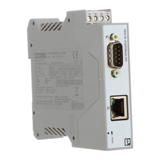
GW DEVICE SERVER... Structure GW DEVICE SERVER 1E/1DB9 The GW DEVICE SERVER 1E/1DB9 features one Ethernet port and one RS-232/422/485 serial port with a D-SUB 9 connector. Figure 1-1 GW DEVICE SERVER 1E/1DB9 Table 1-2 GW DEVICE SERVER 1E/1DB9 structure... -
Page 9: Gw Device Server 1E/2Db9 Structure
GW DEVICE SERVER 1E/2DB9 Table 1-3 GW DEVICE SERVER 1E/2DB9 structure Item Description Power connector P1 D-SUB 9 connector Ethernet port (RJ45) P2 D-SUB 9 connector Status LED Ethernet activity status LED Ethernet link status LED Reset button 3730_en_A PHOENIX CONTACT... -
Page 10: Gw Device Server 2E/2Db9 Structure
Power connector P1 D-SUB 9 connector Ethernet link status LED E2 Ethernet port (RJ45) Ethernet activity status LED Status LED P2 D-SUB 9 connector Ethernet activity status LED E1 Ethernet port (RJ45) Ethernet link status LED Reset button PHOENIX CONTACT 3730_en_A... -
Page 11: Gw Device Server 2E/4Db9 Structure
Ethernet link status LED E2 Ethernet port (RJ45) Ethernet activity status LED P4 D-SUB 9 connector P2 D-SUB 9 connector Status LED Ethernet activity status LED E1 Ethernet port (RJ45) Ethernet link status LED Reset button P1 D-SUB 9 connector 3730_en_A PHOENIX CONTACT... - Page 12 GW DEVICE SERVER... PHOENIX CONTACT 3730_en_A...
-
Page 13: Installation
Hold the device by the housing cover and carefully push the device toward the mounting surface (B). After the foot is snapped onto the DIN rail, verify that it is attached securely. Figure 2-1 DIN rail mounting 3730_en_A PHOENIX CONTACT... - Page 14 Use a suipagele screwdriver to release the locking mechanism (A) on the snap-on foot of the device. Hold onto the device by the housing cover and carefully tilt it upward (B). Remove the device from the DIN rail (C). Figure 2-2 DIN rail removal PHOENIX CONTACT 3730_en_A...
-
Page 15: Data Interfaces
(DCE) (DTE) 1, 6 6, 8 2.3.2 Connecting the RS-422 cable Figure 2-3 Pin 1 location In RS-422 mode, a point-to-point connection can be established. Use a twisted-pair, common shielded bus cable to connect the I/O device. 3730_en_A PHOENIX CONTACT... -
Page 16: Connecting The Rs-485 Cable
Push the Ethernet cable with the crimped RJ45 connector into the GW DEVICE SERVER...until it engages with a click. PHOENIX CONTACT 3730_en_A... - Page 17 (PCs) is subject to the 5-4-3 rule of repeater placement on the network: – Five segments connected on the network. – Four repeaters. – Three segments of the fiber segments can have stations connected. The other two segments must be inter-repeater link segments with no stations connected. 3730_en_A PHOENIX CONTACT...
-
Page 18: Connecting The Power Supply
The GW DEVICE SERVER... is powered using a +24 V DC SELV power supply. The power supply is connected by way of COMBICON plug-in screw terminal blocks (24 V and 0 V). Figure 2-4 Single power supply connection Figure 2-5 Redundant power supply connection PHOENIX CONTACT 3730_en_A... -
Page 19: Configuration And Startup
Set the IP address of the connected PC to the sub-network of the GW DEVICE SERVER…: for example, IP = 192.168.254.10, sub-network = 255.255.255.0. Open a web browser and enter the IP address of the GW DEVICE SERVER… in the “Address” field (default = 192.168.254.254). Figure 3-1 “Login” screen 3730_en_A PHOENIX CONTACT... -
Page 20: Home Screen
Advanced settings can be accessed through the menu at the top of the screen. The “Home” screen can be accessed at any time by clicking the “Home” button in the upper left corner of the web-based management interface. PHOENIX CONTACT 3730_en_A... -
Page 21: General Settings
The field accepts up to 16 characters. LAN settings 3.6.1 IP address To enter the IP address: From the “LAN Settings” page, click the “IP Address” tab to access the “IP Address” page. Figure 3-4 “LAN Settings/IP Address” page 3730_en_A PHOENIX CONTACT... -
Page 22: Security
It is used by some cipher suites to encrypt the SSL/TLS handshaking messages. Possession of the private portion of this key pair allows an eavesdropper to decrypt traffic on SSL/TLS connections that use RSA encryption during handshaking. PHOENIX CONTACT 3730_en_A... - Page 23 All GW DEVICE SERVER... units are shipped from the factory with identical configurations. They all have the identical, self-signed, Phoenix Contact Server RSA Certificates, Server RSA Keys, Server DH Keys, and no Client Authentication Certificates. For maximum data and access security, you should configure all GW DEVICE SERVER...
-
Page 24: Serial Settings
Click the appropriate configuration tab to edit the configuration of that port. Figure 3-6 “Serial Settings/Overview” page 3.7.1 Port configuration Figure 3-7 “Serial Settings/Port 1 Configuration” page PHOENIX CONTACT 3730_en_A... -
Page 25: Serial Port Configuration" Group
RTS turned on when a connection is established on this port. Use toggle to turn RTS on when data is being transmitted and turned off upon completion of data transmission. The RTS Mode “Toggle” may be used only when Flow Control is set to None. 3730_en_A PHOENIX CONTACT... -
Page 26: Enable Tcp Connection" Group
Enable TCP Connection: This must be enabled to use the port as a socket or to use security with the Windows driver. Listen: Check the “Listen” box so that the GW DEVICE SERVER... listens for incoming TCP/IP socket connections on the port number specified in the “On Port” field. PHOENIX CONTACT 3730_en_A... - Page 27 The UDP connection provides a very flexible means of managing Ethernet traffic to and from the GW DEVICE SERVER..Data flow from Ethernet to serial, or vice versa, can be managed to send data to specific devices or receive. Enable UDP Connection: Check the box to enable UDP connections. 3730_en_A PHOENIX CONTACT...
-
Page 28: Diagnostics
Ethernet network if Allow Ethernet data from any IP Address is selected. Diagnostics To view any diagnostics data: Click the “Diagnostics” tab to view a variety of packet statistics that can be used to diagnose a configuration or application problem. Figure 3-11 “Diagnostics” page PHOENIX CONTACT 3730_en_A... - Page 29 Set the “Log history” field to configure the maximum number of lines captured by the monitor before the oldest entries are removed. The monitor capture can also be saved as a .txt file for later review or analysis. 3730_en_A PHOENIX CONTACT...
-
Page 30: Maintenance
The “Password” field is case sensitive. The user name is fixed and cannot be modified. To change a password, enter the current password and the new password (twice) in the appropriate fields. Click the “Apply Changes” button to save changes. PHOENIX CONTACT 3730_en_A... -
Page 31: Restore Defaults
3.9.3 Log files To view log files: From the “Device Maintenance” page, click the “Log Files” tab to review the log files of the device, which can be used for advanced troubleshooting. Figure 3-15 “Maintenance/Log Files” page 3730_en_A PHOENIX CONTACT... -
Page 32: Configuration Files
To load a configuration file to a GW DEVICE SERVER..., click “Browse” to open a dialog box and browse to the configuration file location on the PC. After selecting the appropriate configuration file, enter the password for the file and click “Load Configuration.” PHOENIX CONTACT 3730_en_A... -
Page 33: Update Firmware
Click the “Apply Changes” button to install the firmware. NOTE: Ensure that a reliable power connection is available during the firmware update. Do not restart the module or disconnect the Ethernet cable during this process When firmware is updated, the device configuration is maintained. 3730_en_A PHOENIX CONTACT... - Page 34 GW DEVICE SERVER... PHOENIX CONTACT 3730_en_A...
-
Page 35: Application Examples
Connection establishment can be controlled by various conditions. The UDP protocol is connectionless, and data is transmitted as soon as it appears at the V.24 (RS-232) interface. It can be used in multiple unidirectional or bidirectional configurations, including point-to-point and point-to-multipoint. 3730_en_A PHOENIX CONTACT... -
Page 36: Settings In Tcp Mode
Device A initiates the connection to device B Connect Select how the connection – Device A initiates the connection to is initiated device B Disconnect Select how the connection – Device A initiates the connection to is disconnected device B PHOENIX CONTACT 3730_en_A... -
Page 37: Unidirectional Point-To-Multipoint Settings In Udp Mode
Device A sends data to device B UDP Listen port – 3001 Device B should listen for UDP traffic on this port number Device B, C, D, etc., could be multiple serial ports on the same GW DEVICE SERVER... 3730_en_A PHOENIX CONTACT... -
Page 38: Bidirectional Point-To-Multipoint Settings In Udp Mode
Device A sends data to device B UDP Listen port 3001 3001 Device B should listen for UDP traffic on this port number Device B, C, D, etc., could be multiple serial ports on the same GW DEVICE SERVER... PHOENIX CONTACT 3730_en_A... -
Page 39: Unidirectional Multipoint-To-Point Settings In Udp Mode
Devices A and B send data to each other UDP Listen port 3001 3001 Device B should listen for UDP traffic on this port number Device B is a multiport GW DEVICE SERVER..The UDP setting for each serial port should be the same. 3730_en_A PHOENIX CONTACT... -
Page 40: Bidirectional Multipoint-To-Point Settings In Udp Mode
UDP Listen port 3005 3001 (serial port 1) Devices should listen for UDP traffic on these port numbers 3002 (serial port 2) 3003 (serial port 3) 3004 (serial port 4) Device B is a multiport GW DEVICE SERVER..PHOENIX CONTACT 3730_en_A... -
Page 41: Virtual Com Port
Target port – Source port – Connect Data The connection is started when the COM port redirector sends data Disconnect Idle If no data is received for the period set by the Idle Timer field, disconnect 3730_en_A PHOENIX CONTACT... -
Page 42: Windows Drivers
Windows operating system from the remote GW DEVICE SERVER... and is the recommended software for any timing-sensitive applications requiring true COM port communication and/or secure connections. It is supported on Windows 7/8/10 operating systems. For further configuration information, refer to the GW DEVICE SERVER... Windows Driver manual. PHOENIX CONTACT 3730_en_A... -
Page 43: Troubleshooting
An internal error is indicated by three flashes every five seconds. Green Link LED. On indicates Ethernet network is connected. Yellow Activity LED. Flashing indicates data transfer activity. LEDs on Ethernet ports are not labeled. See Section 1.1, “Structure” for LED location. 3730_en_A PHOENIX CONTACT... - Page 44 GW DEVICE SERVER... PHOENIX CONTACT 3730_en_A...
-
Page 45: Appendixes
A Appendixes List of figures Section 1 Figure 1-1: GW DEVICE SERVER 1E/1DB9 ............4 Figure 1-2: GW DEVICE SERVER 1E/2DB9 ............5 Figure 1-3: GW DEVICE SERVER 2E/2DB9 ............6 Figure 1-4: GW DEVICE SERVER 2E/4DB9 ............7 Section 2 Figure 2-1: DIN rail mounting .................. - Page 46 GW DEVICE SERVER... Section 4 Figure 4-1: Serial tunneling ................... 31 Figure 4-2: Virtual COM ports ................37 Figure 4-3: “Create New Port” dialog box .............. 38 PHOENIX CONTACT 3730_en_A...
-
Page 47: List Of Page
List of page Section 1 Table 1-1: GW DEVICE SERVER...types ............... 3 Table 1-2: GW DEVICE SERVER 1E/1DB9 structure..........4 Table 1-3: GW DEVICE SERVER 1E/2DB9 structure..........5 Table 1-4: GW DEVICE SERVER 2E/2DB9 structure..........6 Table 1-5: GW DEVICE SERVER 2E/4DB9 structure..........7... - Page 48 GW DEVICE SERVER... PHOENIX CONTACT 3730_en_A...
Need help?
Do you have a question about the GW DEVICE SERVER 1E/1DB9 and is the answer not in the manual?
Questions and answers