Phoenix Contact GW PN/DP 1E/1DB9 User Manual
Protocol converter for profinet to profibus dp
Hide thumbs
Also See for GW PN/DP 1E/1DB9:
- User manual (90 pages) ,
- User manual (72 pages) ,
- User manual (52 pages)
Table of Contents
Advertisement
Quick Links
Advertisement
Chapters
Table of Contents

Related Manuals for Phoenix Contact GW PN/DP 1E/1DB9


Summary of Contents for Phoenix Contact GW PN/DP 1E/1DB9
- Page 1 Protocol converter for PROFINET to PROFIBUS DP User manual UM EN GW PN/DP 1E/1DB9...
- Page 2 Protocol converter for PROFINET to PROFIBUS DP UM EN GW PN/DP 1E/1DB9, Revision B 2020-12-22 This user manual is valid for: Designation Version Order No. GW PN/DP 1E/1DB9 1108712 PHOENIX CONTACT GmbH & Co. KG • Flachsmarktstraße 8 • 32825 Blomberg • Germany phoenixcontact.com...
-
Page 3: Table Of Contents
Device maintenance ....................18 4.8.1 Passwords ...................18 4.8.2 Restore defaults ...................19 4.8.3 Log files ....................19 4.8.4 Update firmware ...................20 GSDML file ......................21 4.10 Troubleshooting....................24 4.10.1 Resetting the device ................24 4.10.2 LEDs ....................25 Technical appendix........................27 PROFIBUS slot assignment ................27 3/34 4063_en_B PHOENIX CONTACT... - Page 4 GW PN/DP 1E/1DB9 Appendixes..........................29 List of figures ...................... 29 List of tables ....................... 31 4/34 PHOENIX CONTACT 4063_en_B...
-
Page 5: For Your Safety
Changes or modifications to hardware and software of the device are not permitted. Incorrect operation or modifications to the device can endanger your safety or damage the device. Do not repair the device yourself. If the device is defective, please contact Phoenix Contact. 5/34 4063_en_B... -
Page 6: Safety Regulations And Installation Notes
GW PN/DP 1E/1DB9 Safety regulations and installation notes Installation, operation, and maintenance may be carried out only by qualified electricians. Follow the specified installation instructions. The applicable specifications and safety directives (including the national safety directives), as well as the general technical regulations, must be observed during installation and operation. -
Page 7: Description
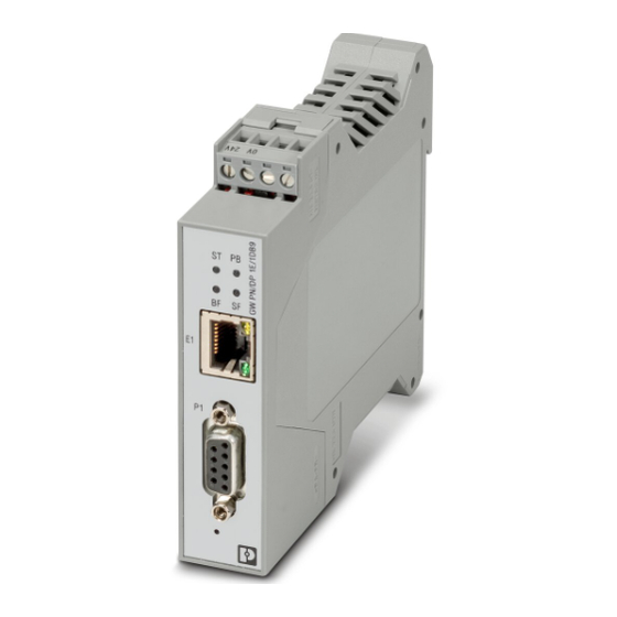
Description Description The GW PN/DP 1E/1DB9 provides a simple way to integrate PROFIBUS DP devices into a PROFINET system. The GW PN/DP 1E/1DB9 supports up to 31 slaves connected directly or a maximum of 125 slaves using repeaters. Connect a PROFINET controller to the GW PN/DP 1E/1DB9 gateway via Ethernet cable. - Page 8 GW PN/DP 1E/1DB9 8/34 PHOENIX CONTACT 4063_en_B...
-
Page 9: Installation
Use a suitable screwdriver to release the locking mechanism (A) on the snap-on foot of the device. Hold on to the device by the housing cover and carefully tilt it upward (B). Remove the device from the DIN rail (C). Figure 3-2 DIN rail removal 9/34 4063_en_B PHOENIX CONTACT... -
Page 10: Data Interface
3.2.2 Connecting the Ethernet cable The GW PN/DP 1E/1DB9 has an Ethernet interface on the front in RJ45 format, to which only twisted-pair cables with an impedance of 100 can be connected. The data transmission rate is either 10 or 100 Mbps. The GW PN/DP 1E/1DB9 supports the auto negotiation function for automatic selection of the transmission speed, as well as an automatic crossover feature for the selection of line or crossover cabling. - Page 11 Installation The device can be connected to a single power source. The power supply is connected by way of a COMBICON plug-in screw terminal blocks (24 V and 0 V). Figure 3-3 Power supply connection 11/34 4063_en_B PHOENIX CONTACT...
- Page 12 GW PN/DP 1E/1DB9 12/34 PHOENIX CONTACT 4063_en_B...
-
Page 13: Configuration And Startup
Login To log in: Set the IP address of the connected PC to the subnetwork of the GW PN/DP 1E/1DB9. For example, IP = 192.168.254.10, subnetwork = 255.255.255.0. Open a web browser and enter the IP address of the GW PN/DP 1E/1DB9 in the “Address”... -
Page 14: Home Page
GW PN/DP 1E/1DB9 If the web server does not load, first check the IP parameters of the PC. If everything is set correctly, check to see if there are any proxy settings loaded in the web browser. The proxy setting must be set to “Load automatically” or “Deactivated” to properly establish communication. -
Page 15: General Settings
Enter the time and date in the appropriate fields. Use PC Clock Transfers the current time and date from a connected PC to the GW PN/DP 1E/1DB9. Use NTP Server The time and date are downloaded from the server(s) specified in the “Time Server 1” and “Time Server 2” fields. -
Page 16: Lan Settings
GW PN/DP 1E/1DB9 LAN settings The “LAN Settings” page displays the MAC address. The IP address must be set using DCP settings. Figure 4-4 “LAN Settings” page Diagnostics The “Diagnostics” page displays the PROFINET diagnostics and PROFIBUS live list. Figure 4-5 “Diagnostics”... - Page 17 PROFIBUS slave is assigned to the correct slot in the PLC project. PROFIBUS bus parameter Master Address Displays the PROFIBUS master address of the GW PN/DP 1E/1DB9. Master Address Displays the PROFIBUS master address of the GW PN/DP 1E/1DB9. 17/34 4063_en_B PHOENIX CONTACT...
-
Page 18: Device Maintenance
Click the “Device Maintenance” tab to access the available maintenance functions of the GW PN/DP 1E/1DB9. 4.8.1 Passwords The GW PN/DP 1E/1DB9 uses an administrator-level password. The administrator level user may make changes to the configuration. Figure 4-6 “Passwords” page To change passwords: From the “Device Maintenance”... -
Page 19: Restore Defaults
Configuration and startup 4.8.2 Restore defaults The “Restore Defaults” page provides the ability to return the GW PN/DP 1E/1DB9 to the factory default settings. Figure 4-7 “Restore Defaults” page From the “Device Maintenance” page, click the “Restore Defaults” tab. Check the “Check the box to confirm…”, and then click the “Apply” button. -
Page 20: Update Firmware
GW PN/DP 1E/1DB9 From the “Device Maintenance” page, click the “Log Files” tab to review the log files. Click the “Syslog” button to open the file in a text editor. All configuration changes made to the system are recorded. 4.8.4... -
Page 21: Gsdml File
GW PL ETH/UNI-BUS head station and the GW PN/DP 1E/1DB9. Figure 4-10 “Project Selection” window Click the radio button under the GW PN/DP 1E/1DB9, and then click the “OK” button. This opens the GSDML Creation Tool window. Figure 4-11 “GSDML gen GSDML Creation Tool”... -
Page 22: Import Gsd Files" Dialog Box
It may be useful to create a file for the GSDML files. The GSDML generator creates three files: – a bmp file for that is an image of the GW PN/DP 1E/1DB9. – an html file that details the PROFIBUS address in relation to the PROFINET slot. - Page 23 Status bar Shows/hides the “Status” bar. Module catalog Shows/hides the window containing the available expansion modules. Not applicable to the GW PN/DP 1E/1DB9. Large icons Presents large icons for the imported PROFIBUS DP slave device GSDs. Small icons Presents small icons for the imported PROFIBUS DP slave devices GSDs.
-
Page 24: Troubleshooting
This method does not require the use of a PC. To force a reset: With the GW PN/DP 1E/1DB9 powered off, press and hold the reset button. Continue to hold the reset button and apply power. The reset button should be held for at least 5 seconds after power is applied. -
Page 25: Leds
Configuration and startup 4.10.2 LEDs The GW PN/DP 1E/1DB9 provides four LEDs. Table 4-2 Status LED descriptions Status Description Normal operation. Solid green Device initializing. Flashing green (1 Hz) Signal request due to DCP request. Flashing red (1 Hz) PROFIBUS controller initialization. - Page 26 GW PN/DP 1E/1DB9 26/34 PHOENIX CONTACT 4063_en_B...
-
Page 27: A Technical Appendix
Technical appendix A Technical appendix PROFIBUS slot assignment Table A-1 PROFIBUS slot assignments PROFINET slot PROFIBUS address Reserved Reserved • • • • • • 27/34 4063_en_B PHOENIX CONTACT... - Page 28 GW PN/DP 1E/1DB9 28/34 PHOENIX CONTACT 4063_en_B...
- Page 29 “Update Firmware” page ..............20 Figure 4-10: “Project Selection” window ..............21 Figure 4-11: “GSDML gen GSDML Creation Tool” window ........21 Figure 4-12: “Import GSD files” dialog box ..............22 Figure 4-13: “Save As” dialog box to export GSDML file .........22 29/34 4063_en_B PHOENIX CONTACT...
- Page 30 GW PN/DP 1E/1DB9 30/34 PHOENIX CONTACT 4063_en_B...
- Page 31 List of tables List of tables Section 2 Table 2-1: UM EN GW PN/DP 1E/1DB9 structure ..........7 Section 3 Table 3-1: RS-485 pinout..................10 Section 4 Table 4-1: GSDML Creation Tool menu structure..........23 Table 4-2: Status LED descriptions ..............25 Section A Table A-1: PROFIBUS slot assignments ...............27...
- Page 32 GW PN/DP 1E/1DB9 32/34 PHOENIX CONTACT 4063_en_B...
- Page 33 The receipt of technical documentation (in particular user documentation) does not constitute any further duty on the part of Phoenix Contact to furnish information on modifications to products and/or technical documentation. You are responsible to verify the suitability and intended use of the products in your specific application, in particular with regard to observing the applicable standards and regulations.
- Page 34 Middletown, PA 17057 Should you have any suggestions or recommendations for improvement of the contents and layout of our manuals, please send your comments to: tecdoc@phoenixcontact.com 34/34 PHOENIX CONTACT GmbH & Co. KG • Flachsmarktstraße 8 • 32825 Blomberg • Germany phoenixcontact.com...
Need help?
Do you have a question about the GW PN/DP 1E/1DB9 and is the answer not in the manual?
Questions and answers