Phoenix Contact GW PN/MODBUS 1E/1DB9 User Manual
Protocol converter for profinet to modbus rtu/ascii/tcp
Hide thumbs
Also See for GW PN/MODBUS 1E/1DB9:
- User manual (90 pages) ,
- User manual (48 pages) ,
- User manual (52 pages)
Advertisement
Quick Links
Advertisement

Related Manuals for Phoenix Contact GW PN/MODBUS 1E/1DB9


Summary of Contents for Phoenix Contact GW PN/MODBUS 1E/1DB9
- Page 1 Protocol converter for PROFINET to Modbus RTU/ASCII/TCP User manual UM EN GW PN/MODBUS...
- Page 2 This user manual is valid for: Designation Order No. GW PN/MODBUS 1E/1DB9 1105707 GW PN/MODBUS 1E/2DB9 1105708 GW PN/MODBUS 2E/2DB9 1105709 GW PN/MODBUS 2E/4DB9 1105710 PHOENIX CONTACT GmbH & Co. KG • Flachsmarktstraße 8 • 32825 Blomberg • Germany phoenixcontact.com...
- Page 3 4.6.1 IP address ....................22 4.6.2 Security ....................23 Serial settings ......................24 4.7.1 Port configuration ................25 Modbus settings ....................29 4.8.1 Modbus TCP configuration ..............30 4.8.2 Remote Modbus addressing ..............31 4.8.3 TCP/IP connection ................33 4.8.4 Device ID aliasing ................35 3/72 4052_en_A PHOENIX CONTACT...
- Page 4 Log files ....................62 4.11.4 Configuration files ................63 4.11.5 Update firmware ...................64 Troubleshooting........................65 Resetting the device ....................65 5.1.1 Hardware reset ..................65 5.1.2 Software reset ..................65 LEDs........................65 Appendixes..........................67 List of figures ...................... 67 List of tables ....................... 69 4/72 PHOENIX CONTACT 4052_en_A...
- Page 5 Changes or modifications to hardware and software of the device are not permitted. Incorrect operation or modifications to the device can endanger your safety or damage the device. Do not repair the device yourself. If the device is defective, please contact Phoenix Contact. 5/72 4052_en_A...
- Page 6 In potentially explosive areas, the reset switch may only be activated when power the device is disconnected. Do not disconnect equipment unless power has been switched off or the area is known to be non-hazardous. Power supply must be from a Class 2, SELV, LPS, or LVLE source. 6/72 PHOENIX CONTACT 4052_en_A...
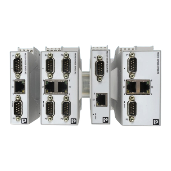
- Page 7 Ethernet ports to fit any application. This user manual is valid for: Table 2-1 GW PN/MODBUS... types Type Description Order No. GW PN/MODBUS 1E/1DB9 1105707 GW PN/MODBUS 1E/2DB9 1105708 GW PN/MODBUS 2E/2DB9 1105709 GW PN/MODBUS 2E/4DB9...
- Page 8 GW PN/MODBUS... Structure GW PN/MODBUS 1E/1DB9 The GW PN/MODBUS 1E/1DB9 features one Ethernet port and one RS-232/422/485 serial port with a D-SUB 9 connector. Figure 2-1 GW PN/MODBUS 1E/1DB9 Table 2-2 GW PN/MODBUS 1E/1DB9 structure Item Description Power connector P1 D-SUB 9 connector...
- Page 9 GW PN/MODBUS 1E/2DB9 Table 2-3 GW PN/MODBUS 1E/2DB9 structure Item Description Power connector P1 D-SUB 9 connector Ethernet port (RJ45) P2 D-SUB 9 connector Status LED Ethernet activity status LED Ethernet link status LED Reset button 9/72 4052_en_A PHOENIX CONTACT...
- Page 10 P1 D-SUB 9 connector Ethernet link status LED E2 Ethernet port (RJ45) Ethernet activity status LED P2 D-SUB 9 connector Status LED Ethernet activity status LED E1 Ethernet port (RJ45) Ethernet link status LED Reset button 10/72 PHOENIX CONTACT 4052_en_A...
- Page 11 E2 Ethernet port (RJ45) Ethernet activity status LED P4 D-SUB 9 connector P2 D-SUB 9 connector Status LED Ethernet activity status LED E1 Ethernet port (RJ45) Ethernet link status LED Reset button P1 D-SUB 9 connector 11/72 4052_en_A PHOENIX CONTACT...
- Page 12 GW PN/MODBUS... 12/72 PHOENIX CONTACT 4052_en_A...
- Page 13 Hold the device by the housing cover and carefully push the device toward the mounting surface (B). After the foot is snapped onto the DIN rail, verify that it is attached securely. Figure 3-1 DIN rail mounting 13/72 4052_en_A PHOENIX CONTACT...
- Page 14 Use a suitable screwdriver to release the locking mechanism (A) on the snap-on foot of the device. Hold on to the device by the housing cover and carefully tilt it upward (B). Remove the device from the DIN rail (C). Figure 3-2 DIN rail removal 14/72 PHOENIX CONTACT 4052_en_A...
- Page 15 No. 2799474). The cable is an interface cable with 1:1 connected contacts. Table 3-1 D-SUB 9 to RS-232 pin out GW PN/MODBUS... End device RS-232 Signal D-SUB 9 D-SUB 9 (DTE) direction (DCE) (DTE) <– <– –> –> 1, 6 <– –> <– <– 15/72 4052_en_A PHOENIX CONTACT...
- Page 16 Fit this bus cable with a termination network at the two furthest points of the RS-485 network. The termination resistors are integrated in the GW PN/MODBUS... and can be switched on through the web-based management interface. 16/72 PHOENIX CONTACT 4052_en_A...
- Page 17 The maximum number of segments connected on a network is five. – Four repeaters is the maximum that can be applied to a network. – Only three segments can have user connections. The other two segments must act as repeaters with no user connections. 17/72 4052_en_A PHOENIX CONTACT...
- Page 18 The GW PN/MODBUS... is powered using a +24 V DC SELV power supply. The power supply is connected by way of COMBICON plug-in screw terminal blocks (24 V and 0 V). Figure 3-4 Single power supply connection Figure 3-5 Redundant power supply connection 18/72 PHOENIX CONTACT 4052_en_A...
- Page 19 Set the IP address of the connected PC to the subnetwork of the GW PN/MODBUS...: for example, IP = 192.168.254.10, subnetwork = 255.255.255.0. Open a web browser and enter the IP address of the GW PN/MODBUS... in the “Address” field (default = 192.168.254.254). Figure 4-1 “Login” page 19/72 4052_en_A PHOENIX CONTACT...
- Page 20 Advanced settings can be accessed through the menu at the top of the page. The “Home” page can be accessed at any time by clicking the “Home” button in the upper-left corner of the web-based management interface. 20/72 PHOENIX CONTACT 4052_en_A...
- Page 21 Name configured in the web interface. Contact: Enter the name of a contact person, group, or department responsible for this device. The field accepts up to 16 characters. Click the “Apply Changes” button to save the configuration. 21/72 4052_en_A PHOENIX CONTACT...
- Page 22 MAC Address: The MAC address of the GW PN/MODBUS... is displayed. Click the “Apply Changes” button to save the configuration. . Discover and basic configuration protocol (DCP) settings will overwrite the IP address and the Device Name configured in the web manager. 22/72 PHOENIX CONTACT 4052_en_A...
- Page 23 SSL client if requested by the server. In order to function properly, this certificate must be signed using the RSA server key. This means that the RSA server certificate and RSA server key must be replaced as a pair. 23/72 4052_en_A PHOENIX CONTACT...
- Page 24 Click the “Serial Settings” tab to configure the serial port(s). The “Overview” page provides a quick summary of the current configuration of the serial port(s). Click the appropriate configuration tab to edit the configuration of that port. Figure 4-6 “Serial Settings/Overview” page 24/72 PHOENIX CONTACT 4052_en_A...
- Page 25 To configure serial ports: From the “Serial Settings” page, click the “Port Configuration” tab. In the “Serial Port Configuration” group, specify the settings of each serial port to match the connected serial device. Figure 4-8 “Serial Port Configuration” page 25/72 4052_en_A PHOENIX CONTACT...
- Page 26 If enabled, all packets with parity, framing, or overrun errors are dropped. errors 4.7.1.2 Modbus configuration To configure serial ports: From the “Serial Settings” page, click the “Port Configuration” tab. In the “Modbus Configuration” group, specify Modbus settings. Figure 4-9 “Modbus Configuration” page 26/72 PHOENIX CONTACT 4052_en_A...
- Page 27 ID offset configuration. Select Add to message ID to add the device offset to the message device ID. Select Subtract from message ID to subtract the device ID offset from the message device ID. Select Off to disable this functionality. 27/72 4052_en_A PHOENIX CONTACT...
- Page 28 Check for conflicts with the alias device ID configuration. The device ID offset configuration must coincide with any alias device ID configurations. – Verify that the valid device ID ranges are sufficient to address all serial devices. 28/72 PHOENIX CONTACT 4052_en_A...
- Page 29 The “Overview” page provides a quick summary of the current configuration of the serial port(s). Click the appropriate configuration tab to edit the Modbus configuration. Figure 4-10 “Modbus Overview” page The “Modbus Overview” page provides a brief explanation of each configuration page. 29/72 4052_en_A PHOENIX CONTACT...
- Page 30 Disable gateway prevents the GW PN/MODBUS... from sending exception responses to messages addressed to slave devices not present on the network. – Disable slaves prevents the GW PN/MODBUS... from sending exception responses from slave devices connected to the network. 30/72 PHOENIX CONTACT 4052_en_A...
- Page 31 If selected, a dedicated Modbus TCP connection is used to connect to this remote device. This is most commonly used when connecting to another gateway, multiple devices are being accessed, and maximum bandwidth is desired. range. 31/72 4052_en_A PHOENIX CONTACT...
- Page 32 To delete an entry, click the “Delete Entry” check box next to the row to remove, and then click the “Apply Changes” button. To delete the entire table, check the “Delete all entries” box, and then click the “Apply Changes” button. 32/72 PHOENIX CONTACT 4052_en_A...
- Page 33 “Listen Port” field. On Port Enter the TCP port number on which the GW PN/MODBUS... listens for connections. Up to six connections from external applications are supported. The Modbus TCP port 502 cannot be used. 33/72 4052_en_A PHOENIX CONTACT...
- Page 34 After entering the parameters, click the “Apply Changes” button to save the configuration. The fields may be edited at any time. Be sure to click the “Apply Changes” button to save the modifications. 34/72 PHOENIX CONTACT 4052_en_A...
- Page 35 ID 50 to 5. Route message with device ID 5. Convert messages with received device ID 100 to 254. Route message with device ID 254. Invalid configuration attempt. No change to device ID is performed. Figure 4-14 “Device ID Alias” page 35/72 4052_en_A PHOENIX CONTACT...
- Page 36 To delete an entry, check the “Delete Entry” box next to the rule to remove it, and then click the “Apply Changes” button. To delete the entire table, check the “Delete all” box, and then click the “Apply Changes” button. 36/72 PHOENIX CONTACT 4052_en_A...
- Page 37 Modbus slave or Shared Memory. The “Modbus to Modbus Configuration” page should be configured in conjunction with the “Shared Memory” page when using GSDML files and PROFINET communication. Figure 4-15 “Modbus to Modbus Configuration” page 37/72 4052_en_A PHOENIX CONTACT...
- Page 38 Enter the rate at which the GW PN/MODBUS... should read the configured Modbus slave or Shared Memory. The maximum poll rate is 20 ms, but the length and baud rate should be considered when setting the poll rate to avoid communication errors. 38/72 PHOENIX CONTACT 4052_en_A...
- Page 39 The “Shared Memory” page contains eight blocks of 200 holding registers and eight blocks of 320 coils. Write access may be controlled to each holding register block and coil block. Each block may be configured to provide all masters write access or be restricted to a specific master. 39/72 4052_en_A PHOENIX CONTACT...
- Page 40 Figure 4-16 “Shared Memory Configuration” page To configure the Shared Memory: From the “Data Mapping Settings” page, click the “Shared memory” tab. In the “Shared Memory Configuration” group, specify settings. Enter information in the fields provided. 40/72 PHOENIX CONTACT 4052_en_A...
- Page 41 If write access is limited to a specific master, enter the serial port or IP address of the master. Description Each block may be labeled with a description, for example, “Compressor Station #1” for simple identification of the registers. 41/72 4052_en_A PHOENIX CONTACT...
- Page 42 GW PN/MODBUS... Click the “Display” button next to each block of shared memory block to view the contents of the memory block. Figure 4-17 “Shared Memory Contents” page showing Holding Registers 42/72 PHOENIX CONTACT 4052_en_A...
- Page 43 Shared Memory address. – Shared Memory block write protection violations: This occurs when a GW PN/MODBUS... configuration can write to a Shared Memory address that is write- protected and there is no write access allowed. 43/72 4052_en_A PHOENIX CONTACT...
- Page 44 Shared Memory Address indicting that Modbus to Modbus Line 2 and Line 3 are reading and writing from overlapping Modbus addresses. Figure 4-20 “Verify Data Mapping” page showing an invalid Shared Memory Address error 44/72 PHOENIX CONTACT 4052_en_A...
- Page 45 The following abbreviations, followed by the command line number, indicate the source of conflicts: – MM Modbus to Modbus – PNIO PROFINET IO Figure 4-21 indicates no conflicts. Figure 4-21 “Shared Memory” page showing no conflicts 45/72 4052_en_A PHOENIX CONTACT...
- Page 46 4.10.1 Communication statistics The “Communication Statistics” page provides an overview of the activity on each serial port and TCP socket connection. Click the “Reset Statistics” button to reset the values to 0. 46/72 PHOENIX CONTACT 4052_en_A...
- Page 47 Overrun Error Count Displays the number of overrun errors received on the serial port. This typically occurs due to one of the following events: incorrect flow control, incorrect baud rate, incorrect data size, or incorrect stop bit setting. 47/72 4052_en_A PHOENIX CONTACT...
- Page 48 The “TCP Statistics” page provides an overview of the activity on each TCP socket connection. The values can be reset to zero at any time by clicking the “Reset Statistics” button. Figure 4-24 “TCP Statistics” page 48/72 PHOENIX CONTACT 4052_en_A...
- Page 49 Displays the IP addresses of remote connections. Status 4.10.1.3 Serial logs The “Serial Logs” page displays the serial messages transmitted and received during normal operation. Click the “Reset Log” button to reset to zero. Figure 4-25 “Serial Logs” page 49/72 4052_en_A PHOENIX CONTACT...
- Page 50 The “Modbus Slaves” page provides device-specific status and statistics for each device connected locally to one or more of the serial ports, or remotely through a remote Modbus TCP device configuration. Click the “Reset Log” button to reset to zero. Figure 4-26 “Modbus Slaves” page 50/72 PHOENIX CONTACT 4052_en_A...
- Page 51 Displays the number of Modbus write messages that were not transmitted for this device. This only occurs when the “Write Mode” option is set to Read Only. Tx Broadcasts Displays the number of Modbus broadcast messages transmitted to this device. 51/72 4052_en_A PHOENIX CONTACT...
- Page 52 Messages Received Displays the total number of Modbus TCP messages received from Modbus TCP master(s). From Modbus TCP Master(s) Responses Sent To Displays the total number of Modbus TCP responses sent to Modbus TCP master(s). TCP Master(s) 52/72 PHOENIX CONTACT 4052_en_A...
- Page 53 To Modbus TCP Slave(s) Modbus TCP Displays the number of Modbus TCP connection attempt problems. This occurs when the device Connection Problems responds and the connection is made, but there are problems setting up the connection. 53/72 4052_en_A PHOENIX CONTACT...
- Page 54 Displays the device ID of the associated device. If device ID offset or alias device ID is enabled, the device ID used to communicate with the device is displayed. Time Since Open This is the time that has elapsed since the connection was opened. 54/72 PHOENIX CONTACT 4052_en_A...
- Page 55 The “Shared Memory” page displays the contents of the Shared Memory block. Use the drop-down menu to navigate to blocks of shared memory. Display Format: Changes the format of the data displayed. Options are: HEX, WORD 16, DWORD 32, STRING. 55/72 4052_en_A PHOENIX CONTACT...
- Page 56 GW PN/MODBUS... Data lines per row: Adjusts the width of the table displayed. Options are: 10, 20. Figure 4-30 “Shared Memory Contents” page displaying Shared Holding Register Block 1 56/72 PHOENIX CONTACT 4052_en_A...
- Page 57 Configuration and startup Figure 4-31 “Shared Memory Contents” page displaying Shared Coil Block 1 57/72 4052_en_A PHOENIX CONTACT...
- Page 58 Displays the number of errors occurred when reading record data. Ethernet port 1 link Displays the link status of Ethernet port 1. status Ethernet port 2 link Displays the link status of Ethernet port 2. status 58/72 PHOENIX CONTACT 4052_en_A...
- Page 59 Displays the minimum, current, and maximum CPU idle count of the GW PN/MODBUS..(min/current/max) Idle count history Displays the average CPU idle count for the last 1, 5, and 15 minutes. (1/5/15) 4.10.4 Data mapping diagnostics 4.10.4.1 Modbus to Tag/File Figure 4-33 Modbus to Tag/File diagnostics 59/72 4052_en_A PHOENIX CONTACT...
- Page 60 Tag/File to Modbus diagnostics Figure 4-34 Tag/File to Modbus diagnostics 4.10.4.3 Modbus to Modbus diagnostics Figure 4-35 Modbus to Modbus diagnostics 4.11 Device maintenance Click the “Device Maintenance” tab to access the available maintenance functions of the GW PN/MODBUS..60/72 PHOENIX CONTACT 4052_en_A...
- Page 61 Click the “Apply Changes” button to save changes. 4.11.2 Restore defaults To restore defaults: From the “Device Maintenance” page, click the “Restore Defaults” tab to return the GW PN/MODBUS... to the original factory defaults, including the IP address. Figure 4-37 “Restore Defaults” page 61/72 4052_en_A PHOENIX CONTACT...
- Page 62 GW PN/MODBUS..The “Device Snapshot” feature allows a user to capture the system log, configuration data, and other information that can be used for advanced troubleshooting or for “As Configured” record-keeping as a single text file. 62/72 PHOENIX CONTACT 4052_en_A...
- Page 63 To load a configuration file to a GW PN/MODBUS..., click the “Browse” button to open a dialog box and browse to the configuration file location on the PC. After selecting the appropriate configuration file, enter the password for the file and click the “Load Configuration” button. 63/72 4052_en_A PHOENIX CONTACT...
- Page 64 NOTE: Ensure that a reliable power connection is available during the firmware update. Do not restart the module or disconnect the Ethernet cable during this process. When the firmware is updated, the device configuration is maintained. 64/72 PHOENIX CONTACT 4052_en_A...
- Page 65 3 flashes per 5 Indicates an internal error seconds LINK Green On solid Indicates Ethernet network is connected Yellow Flashing Flashing indicates data transfer activity LEDs on Ethernet ports are not labeled. See Section 2.1, “Structure” for LED location. 4052_en_A PHOENIX CONTACT...
- Page 66 GW PN/MODBUS... PHOENIX CONTACT 4052_en_A...
- Page 67 Appendixes A Appendixes List of figures Section 2 Figure 2-1: GW PN/MODBUS 1E/1DB9 ..............8 Figure 2-2: GW PN/MODBUS 1E/2DB9 ..............9 Figure 2-3: GW PN/MODBUS 2E/2DB9 ..............10 Figure 2-4: GW PN/MODBUS 2E/4DB9 ...............11 Section 3 Figure 3-1: DIN rail mounting ................13 Figure 3-2: DIN rail removal ..................14...
- Page 68 Figure 4-35: Modbus to Modbus diagnostics ............60 Figure 4-36: “Password” page .................61 Figure 4-37: “Restore Defaults” page ..............61 Figure 4-38: “Log Files” page ..................62 Figure 4-39: “Config Files” page ................63 Figure 4-40: “Update Firmware” page ..............64 68/72 PHOENIX CONTACT 4052_en_A...
- Page 69 List of tables List of tables Section 2 Table 2-1: GW PN/MODBUS... types ..............7 Table 2-2: GW PN/MODBUS 1E/1DB9 structure............8 Table 2-3: GW PN/MODBUS 1E/2DB9 structure............9 Table 2-4: GW PN/MODBUS 2E/2DB9 structure..........10 Table 2-5: GW PN/MODBUS 2E/4DB9 structure..........11 Section 3 Table 3-1: D-SUB 9 to RS-232 pin out ..............15...
- Page 70 GW PN/MODBUS... 70/72 PHOENIX CONTACT 4052_en_A...
- Page 71 The receipt of technical documentation (in particular user documentation) does not constitute any further duty on the part of Phoenix Contact to furnish information on modifications to products and/or technical documentation. You are responsible to verify the suitability and intended use of the products in your specific application, in particular with regard to observing the applicable standards and regulations.
- Page 72 Middletown, PA 17057 Should you have any suggestions or recommendations for improvement of the contents and layout of our manuals, please send your comments to: tecdoc@phoenixcontact.com 72/72 PHOENIX CONTACT GmbH & Co. KG • Flachsmarktstraße 8 • 32825 Blomberg • Germany phoenixcontact.com...
Need help?
Do you have a question about the GW PN/MODBUS 1E/1DB9 and is the answer not in the manual?
Questions and answers