Table of Contents
Advertisement
Quick Links
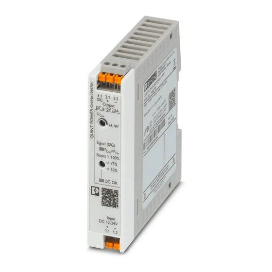
QUINT4-PS/12-24DC/5-15DC/2.5/
PT
DC/DC converter
Data sheet
110260_en_00
1
Description
QUINT POWER power supplies are exceptionally small yet
offer superior system availability in the sub 100 W power
range.
Powerful
–
Static boost of up to 125% (P
–
Dynamic boost of up to 200% (P
Space-saving
–
Slim design
–
Slim design for 120 mm control boxes
Preventive
–
Function monitoring through adjustable signaling of
power thresholds or output voltage
Flexible connection technology
–
Tried-and-tested screw connection
–
Fast Push-in connection
Durable
–
Efficiency up to 92%
–
Low power dissipation
All technical specifications are nominal and refer to a room temperature of 25 °C and 70% relative humidity at
100 m above sea level.
© PHOENIX CONTACT
) for a sustained period
N
) for 4.9 s
N
2021-07-23
Technical data (short form)
Input voltage range
Mains buffering
Nominal output voltage (U
)
N
Setting range of the output voltage
(U
)
Set
Nominal output current (I
)
N
Static Boost (I
)
Stat.Boost
Dynamic Boost (I
)
Dyn.Boost
Output power (P
)
N
Output power (P
)
Stat. Boost
Output power (P
)
Dyn. Boost
Efficiency
Residual ripple
MTBF (IEC 61709, SN 29500)
Ambient temperature (operation)
Dimensions W/H/D
Weight
12 V DC ... 24 V DC -25 % ... +33 %
typ. 20 ms (24 V DC)
12 V DC
5 V DC ... 15 V DC
2.5 A
3.125 A (≤ 40 °C)
5 A (≤ 60 °C (4,9 s))
30 W
37.5 W
60 W
typ. 92.2 % (12 V DC)
< 20 mV
PP
> 1590000 h (40 °C)
-25 °C ... 70 °C
-40°C (startup type tested)
> 60 °C Derating: 2.5 %/K
22.5 mm / 106 mm / 90 mm
0.173 kg
Advertisement
Table of Contents

Related Manuals for Phoenix Contact QUINT4-PS/12-24DC/5-15DC/2.5/ PT


Summary of Contents for Phoenix Contact QUINT4-PS/12-24DC/5-15DC/2.5/ PT
-
Page 1: Description
QUINT4-PS/12-24DC/5-15DC/2.5/ DC/DC converter Data sheet 110260_en_00 © PHOENIX CONTACT 2021-07-23 Description QUINT POWER power supplies are exceptionally small yet offer superior system availability in the sub 100 W power Technical data (short form) range. Input voltage range 12 V DC ... 24 V DC -25 % ... +33 % Mains buffering typ. -
Page 2: Table Of Contents
Structure of the power supply ....................15 Mounting/removing the power supply ..................18 Device connection terminal blocks ..................20 Output characteristic curves ....................20 Boost currents ........................21 Signaling..........................23 Operating modes ........................25 Derating..........................27 110260_en_00 PHOENIX CONTACT 2/30... -
Page 3: Ordering Data
Nominal voltage: 24 V AC/DC The range of accessories is being continuously extended. The current range of accessories can be found in the download area for the product. 110260_en_00 PHOENIX CONTACT 3/30... -
Page 4: Technical Data
Input protection , DC ( to be connected externally upstream ) Input current I Neozed fuse Circuit breaker Power switch Input protection or equivalent ≤ 13 x I Characteristics (maximum magnetic tripping) 16 A 110260_en_00 PHOENIX CONTACT 4/30... - Page 5 Conductor cross section flexible, with ferrule with plastic 0.5 mm² ... 2.5 mm² sleeve Conductor cross section flexible, with ferrule without 0.5 mm² ... 2.5 mm² plastic sleeve Conductor cross section AWG 22 ... 14 Stripping length 10 mm 110260_en_00 PHOENIX CONTACT 5/30...
- Page 6 > 0.9 x U LED lights up green < 0.9 x U LED flashes green Signal output (configurable) Digital 0 V DC / 24 V DC , 22 mA Default 24 V DC , 22 mA ( 24 V DC for U > 0.9 x U 110260_en_00 PHOENIX CONTACT 6/30...
- Page 7 Dimensions W / H / D (state of delivery) 22.5 mm / 106 mm / 90 mm Weight 0.173 kg Power dissipation 12 V DC Maximum power dissipation in no-load condition < 0.5 W Power loss nominal load max. < 2.7 W 110260_en_00 PHOENIX CONTACT 7/30...
- Page 8 < 15 Hz, ±2.5 mm amplitude; 15 Hz ... 100 Hz: 2.3 g 90 Min. (in accordance with IEC 60068-2-6) Shock 18 ms, 30g, in each space direction (according to IEC 60068- 2-27) Degree of pollution Climatic class 3K3 (in acc. with EN 60721) Overvoltage category EN 61010-1 II (≤ 5000 m) 110260_en_00 PHOENIX CONTACT 8/30...
- Page 9 UL Listed UL 61010-2-201 CAN/CSA C22.2 No. 61010-2-201:18 UL 121201 & CSA C22.2 No. 213-17 Class I, Division 2, Groups A, B, C, D T4 (Hazardous Location) CB Scheme IEC 61010-1 IEC 61010-2-201 Shipbuilding DNV GL Current approvals/permissions for the product can be found in the download area under phoenixcontact.net/products 110260_en_00 PHOENIX CONTACT 9/30...
- Page 10 Output 2 kV (Test Level 3 - 2 kV (Test Level 4 - asymmetrical) asymmetrical) Signal 1 kV (Test Level 3 - 2 kV (Test Level 4 - asymmetrical) asymmetrical) Comments Criterion B Criterion B 110260_en_00 PHOENIX CONTACT 10/30...
- Page 11 EN 61000-6-5 Pulse-shape magnetic field EN 61000-4-9 not required 1000 A/m Comments none Criterion A Damped oscillating magnetic field EN 61000-4-10 not required 100 kHz 100 A/m not required 1 MHz 100 A/m Comments none Criterion A 110260_en_00 PHOENIX CONTACT 11/30...
- Page 12 Temporary impairment to operational behavior that is corrected by the device itself. Criterion C Temporary adverse effects on the operating behavior, which the device corrects automatically or which can be restored by actuating the operating elements. 110260_en_00 PHOENIX CONTACT 12/30...
-
Page 13: Safety And Installation Notes
The power supply is maintenance-free. Repairs may only be carried out by the manufacturer. The warranty no longer applies if the housing is opened. – The power supply may only be used for its intended use. 110260_en_00 PHOENIX CONTACT 13/30... -
Page 14: High-Voltage Test (Hipot)
Signal contacts Blue Potential 1 - Electrical equipment of machines) the power supply can be High-voltage disconnected during the high-voltage test and only installed tester once the high-voltage test has been completed. DC input circuit Red Potential 2 110260_en_00 PHOENIX CONTACT 14/30... -
Page 15: Structure Of The Power Supply
Connection terminal block input voltage: Input +/- Signaling DC OK LED Rotary selector, status of the output voltage (DC OK) or output power (P > P Signaling P > P LED (yellow): output power > output power threshold P Potentiometer output voltage 110260_en_00 PHOENIX CONTACT 15/30... - Page 16 15 mm. Figure 5 Device dimensions and minimum keep-out areas (in mm) 22,5 3.1 2.1 2.2 Output DC Signal (SIG) > P Boost > 100% > 75% > 50% DC OK Input D C 1.1 1.2 110260_en_00 PHOENIX CONTACT 16/30...
- Page 17 Inrush current limitation PNP transistor switch output Switching transistor and main transmitter (electrically isolating) Rotary selector switch Secondary rectification and smoothing Signal/display LEDs Filter Potentiometer output voltage Optocoupler (electrically isolating) Additional regulatory protection against surge voltage 110260_en_00 PHOENIX CONTACT 17/30...
-
Page 18: Mounting/Removing The Power Supply
Then press the power supply down until the integrated snap-on foot audibly latches into place (B). Check that the power supply is securely attached to the DIN rail. Figure 7 Snapping the power supply onto the DIN rail Click 110260_en_00 PHOENIX CONTACT 18/30... - Page 19 Secure connection wiring with cable binder 3 . 1 2 . 1 S I G 2 . 2 − t p u - 2 8 S i g l ( S > P t > > 7 110260_en_00 PHOENIX CONTACT 19/30...
-
Page 20: Device Connection Terminal Blocks
Dyn. Boost The output voltage is adjusted using the potentiometer. Protection of the secondary side The power supply is electronically short-circuit-proof and t [s] no-load-proof. In the event of an error, the output voltage is limited 110260_en_00 PHOENIX CONTACT 20/30... -
Page 21: Boost Currents
Basic curve of the dynamic boost process 11.2.2 Recovery times at an ambient temperature of 60 °C Figure 17 Required recovery times at ≤ 60°C Dyn.Boost Dyn.Boost Dyn.Boost Dyn. Boost Based Load Dyn. Boost Pause Base Load t [s] 110260_en_00 PHOENIX CONTACT 21/30... - Page 22 ) of 5 A increases for 2 s (t ). After Dyn. Boost Dyn. Boost a recovery time (t ) of 6 s, the dynamic boost is available Pause once again. Figure 18 Example recovery time for ≤ 40°C Dyn. Boost Based Load Dyn. Boost 110260_en_00 PHOENIX CONTACT 22/30...
-
Page 23: Signaling
> P yellow Signal SIG: P > P active high active low active low default LED off green LED: DC OK LED on LED flashing Signal SIG: DC OK active high active high default active low 110260_en_00 PHOENIX CONTACT 23/30... - Page 24 "3.1 SIG" and "2.2 -" or 2.3 -". The maximum world. load is 30 mA. Use Phoenix Contact surge protection (Order No. 2905223) when you are using connection terminal blocks "3.1 SIG" Figure 21 Signaling and "2.2 -"...
-
Page 25: Operating Modes
Using the same cable lengths for the DC convergence point Operating power supplies in the same temperature environment When three or more power supplies are connected in parallel, each output must be protected (e.g., with circuit breakers or decoupling modules) 110260_en_00 PHOENIX CONTACT 25/30... - Page 26 Using the signaling settings, you can monitor whether both power supplies are being operated with ≤ half the nominal load. In the case of system extension, an overload is prevented if one of the power supplies fails. 110260_en_00 PHOENIX CONTACT 26/30...
-
Page 27: Derating
Output power depending on the ambient temperature 100 % 60 °C 125 % 40 °C Stat. 200 % 60 °C Dyn. 200% Dyn. Boost 1000 2000 3000 4000 5000 H [m] 125% Stat. Boost 100% T [°C] 110260_en_00 PHOENIX CONTACT 27/30... - Page 28 The recommended output power for different mounting positions and ambient temperatures can be found in the characteristic curves below. Exceeding these values will reduce the service life of the power supply. 14.3.1 Normal mounting position 14.3.2 Rotated mounting position 90° Z-axis 110260_en_00 PHOENIX CONTACT 28/30...
- Page 29 QUINT4-PS/12-24DC/5-15DC/2.5/PT 14.3.3 Rotated mounting position 180° Z-axis 14.3.4 Rotated mounting position 270° Z-axis 110260_en_00 PHOENIX CONTACT 29/30...
- Page 30 QUINT4-PS/12-24DC/5-15DC/2.5/PT 14.3.5 Rotated mounting position 90° X-axis 100 % 125 % Stat. 200 % Dyn. [°C] 14.3.6 Rotated mounting position 270° X-axis PHOENIX CONTACT GmbH & Co. KG • 32823 Blomberg • Germany 110260_en_00 30/30 phoenixcontact.com...
Need help?
Do you have a question about the QUINT4-PS/12-24DC/5-15DC/2.5/ PT and is the answer not in the manual?
Questions and answers