
Related Manuals for Fuji Electric NRF51


Summary of Contents for Fuji Electric NRF51
- Page 1 User’s Manual Electronic Personal Dosimeter (For Gamma(X)-ray and neutron) NRF51 TN5A4215b 1/58 Fuji Electric Co., Ltd.
- Page 2 Introduction This User’s Manual explains the operation of the Electronic Personal Dosimeter NRF51 (For Gamma(X)-ray and neutron). It provides descriptions of parts, functions and operational instructions for optimal use. Please make sure that you read this manual carefully before operation.
- Page 3 Handling Precaution Please observe the following handling precautions to ensure that you use the NRF51 Electronic Personal Dosimeter safely and avoid injury/damages. Failure to comply with the instructions contained in this manual may reduce the safety of the instrument. Please read this User’s Manual carefully to understand all the precautions before using the NRF51 Electronic Personal Dosimeter.
-
Page 4: Table Of Contents
Contents Overview ............................5 Contents ............................6 Standard product package ......................6 Model ............................. 6 Precautions ............................7 Operational conditions* ......................... 7 Other requirements ........................7 Description of Parts and Functions ....................8 Part names ............................ 8 Display function ........................... 10 Buzzer function ........................... -
Page 5: Overview
By using the Dosimeter Configuration Tool and a PC, it is able to write PC-edited setting values to NRF51 and read measurement trend data from the NRF51 via communication with the device. If it’s worn tightly to the body, energy characteristic of the NRF51 enables direct reading of personal dose equivalent Hp(10). -
Page 6: Contents
Contents Standard product package (1) NRF51 1 pc (2) Accessory ・Battery (AA alkaline battery) 2 pcs Model NRF51 TN5A4215b 6/58... -
Page 7: Precautions
(1) See User’s Manual of “Dosimeter Configuration Tool” for information on parameter writing and data reading via the device and a PC. (2) Try turn OFF & ON the NRF51 if you encounter technical problems. See the “Troubleshooting Table” if the problem is not recovered. -
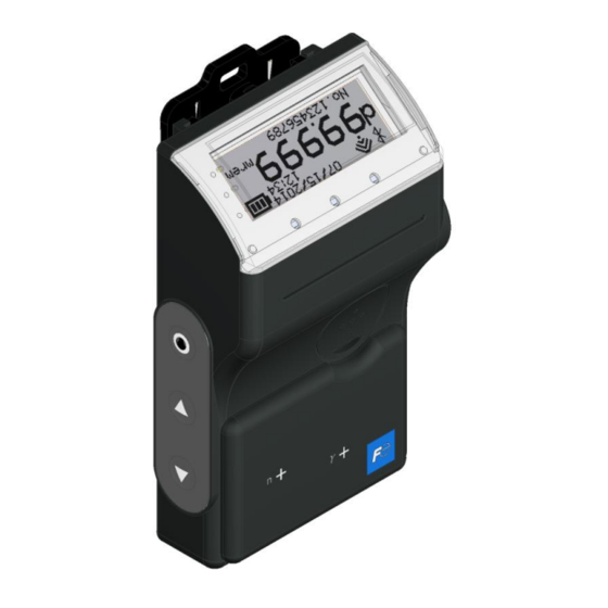
Page 8: Description Of Parts And Functions
Description of Parts and Functions Part names Flash LED Auxiliary LED Operating buttons Clip Battery cap Call button USB connector 21.8 Calibration mark Buzzer TN5A4215b 8/58... - Page 9 If user does not use this emergency alarm, the function can be made void by the Dosimeter Configuration Tool. 11. Clip : To fix the NRF51 on the chest pocket or on the waist belt. TN5A4215b 9/58...
-
Page 10: Display Function
Display function LCD Indication ■Normal condition Date indication Icon area Battery life indication [Note1] [Note2] d: Accumulated dose Accumulated dr: Dose Rate dose *[D/DR] is selectable Dose rate instead of [d/dr] via Dosimeter Configuration Tool Hp10: gamma Unit of measurement Hp10n: neutron ■Alarm condition Icon area... -
Page 11: Buzzer Function
Audible signals sound under the following circumstances: Circumstance Audible signal sounds when Beep pattern Turn ON/OFF NRF51 is turned on Beep 30msec Data changed Setting values of NRF51 have been changed 30msec successfully using a Dosimeter Configuration Tool Beep Beep 500msec 500msec TN5A4215b 11/58... - Page 12 4.3.2 Audible alarms Alarm activation and beep pattern are configurable by user with Dosimeter Configuration Tool. The items that can be set are as follows: (1) Operation timing of LED, Vibrator and Buzzer Operating timing setting is selectable from the following 6 patterns for each alarm type, but pattern No.6 can be selected by “Low battery voltage”...
- Page 13 [Pattern No.5] … When alarm is generated, the operating timing is showed below. [Pattern No.6] … When alarm is generated, the operating timing is showed below. (2) Buzzer frequency Buzzer frequency setting is selectable from the following two settings for each alarm type. [High] …...
- Page 14 [WHITE] … When alarm is generated, white backlight flashes. (5) Sounding time Sounding time setting is selectable from the following settings for each alarm type. [Continuous] … When buzzer sound setting is “ON”, buzzer sounds continuously in alarm condition. [1 min] to [15 min] … When buzzer sound setting is “ON”, buzzer sounds for set period and then buzzer stops.
- Page 15 When multiple alarms happen, alarm pattern is determined by alarm priority. Alarm priorities are as follows: Priority Alarm Remarks Memory error Breakdown RTC error Breakdown Device error Component failure Battery empty Emergency alarm Detector optical check error Neutron accumulated dose overload Gamma-ray accumulated dose overload Neutron dose rate overload Gamma-ray dose rate overload...
- Page 16 Initial settings of alarm operation for each alarm type are as follows: Dose (rate) alarm Alarm type Initial setting of alarm operation Accumulated (1) Operation timing dose alarm [Pattern No.3] (2) Buzzer frequency (3) Buzzer sound (4) Backlight (5) Sounding time [High] [ON] [RED]...
- Page 17 Alarm type Initial setting of alarm operation Dose rate (1) Operation timing alarm [Pattern No.2] (2) Buzzer frequency (3) Buzzer sound (4) Backlight (5) Sounding time [High] [ON] [RED] [Continuous] (6) Mute (7) Vibrator (8) Flash LED (9) Latch [Not available] [ON] [ON] [ON]...
- Page 18 Operation time alarm Alarm type Initial setting of alarm operation Time alarm (1) Operation timing [Pattern No.1] (2) Buzzer frequency (3) Buzzer sound (4) Backlight (5) Sounding time [High] [ON] [RED] [Continuous] (6) Mute (7) Vibrator (8) Flash LED (9) Latch [Not available] [ON] [ON]...
- Page 19 Low battery voltage Alarm type Initial setting of alarm operation Low battery (1) Operation timing voltage [Pattern No.6] (2) Buzzer frequency (3) Buzzer sound (4) Backlight (5) Sounding time [High] [ON] [OFF] [Continuous] (6) Mute (7) Vibrator (8) Flash LED (9) Latch [Not available] [OFF]...
- Page 20 Indication of abnormality Alarm type Initial setting of alarm operation Detector optical (1) Operation timing Check error [Pattern No.4] (2) Buzzer frequency (3) Buzzer sound (4) Backlight (5) Sounding time [High] [ON] [RED] [Continuous] (6) Mute (7) Vibrator (8) Flash LED (9) Latch [Not available] [ON]...
- Page 21 Alarm type Initial setting of alarm operation RTC error (1) Operation timing [Pattern No.4] (2) Buzzer frequency (3) Buzzer sound (4) Backlight (5) Sounding time [High] [ON] [RED] [Continuous] (6) Mute (7) Vibrator (8) Flash LED (9) Latch [Not available] [ON] [ON] (10) LCD indication sample...
- Page 22 Call button action Alarm type Initial setting of alarm operation Emergency alarm (1) Operation timing [Pattern No.5] (2) Buzzer frequency (3) Buzzer sound (4) Backlight (5) Sounding time [High] [ON] [RED] [Continuous] (6) Mute (7) Vibrator (8) Flash LED (9) Latch [Not available] [ON] [ON]...
- Page 23 Notification Alarm type Initial setting of alarm operation Calibration due (1) Operation timing expiration [Pattern No.1] (2) Buzzer frequency (3) Buzzer sound (4) Backlight (5) Sounding time [High] [ON] [YELLOW] [Continuous] (6) Mute (7) Vibrator (8) Flash LED (9) Latch [Not available] [ON] [ON]...
- Page 24 Alarm type Initial setting of alarm operation Bluetooth (1) Operation timing communication [Pattern No.1] error (Component failure is detected at startup) (2) Buzzer frequency (3) Buzzer sound (4) Backlight (5) Sounding time [High] [OFF] [YELLOW] [Continuous] (6) Mute (7) Vibrator (8) Flash LED (9) Latch [Not available]...
- Page 25 4.3.3 Monitoring Sound Buzzer sounds 1 time for a short period, if accumulated dose reaches a preset value of dose interval for monitoring sound. Monitoring sound interval can be chosen from six types, “OFF”, “100 uSv (10 mrem)”, “10 uSv (1 mrem)”, “1 uSv (0.1 mrem)”, “0.2 uSv (0.02 mrem)” and “0.1 uSv (0.01 mrem)”. Please see User’s Manual of “Dosimeter Configuration Tool”...
-
Page 26: Communication Function
(2) Wi-Fi communication setting should be “ON” by user with Dosimeter Configuration Tool. (3) When the setting is “ON”, NRF51 starts connection with cloud server via Wi-Fi access point. After connection establishment, NRF51 sends telemetry data with selected transmission interval and data format. - Page 27 (4) No icon: OFF Please make sure that there is no obstacle such as a metal object between NRF51 and Wi-Fi access point in Wi-Fi communication. If there is the obstacle, Attention communication may be unstable and sending data may be lost.
- Page 28 (1) Bluetooth communication setting should be “ON” by user with Dosimeter Configuration Tool. (2) When the setting is “ON”, NRF51 starts connection with heart rate monitor. After connection establishment, NRF51 receives the heart beat data from heart rate monitor and sends telemetry data with selected transmission interval and data format.
- Page 29 (2) NRF51 should be connected PC with USB cable. (3) Setting parameter can be changed by user with Dosimeter Configuration Tool in the same way as using infrared communication. Also, NRF51 starts transmission of telemetry data periodically when USB telemetry mode setting is “ON”.
- Page 30 4.4.4 Infrared communication function 4.4.4.1 Instructions for use (1) NRF51 should be placed so as that infrared window of NRF51 is opposite to Infrared. (See P.8 and P.9) (2) Setting parameter can be changed by user with Dosimeter Configuration Tool.
-
Page 31: Parts Replacement
* NRF51 can be operated even by one battery. Battery polarity sign Coin driver 1. When replacing batteries, make sure to turn off NRF51. 2. During replacement, align the battery polarity correctly. 3. Use only AA Alkaline battery. 4. When replacing batteries, both batteries must be changed at the same Attention time. -
Page 32: Clip Replacement
Top view Removal of the clip [Mounting of the clip] (1) Push the clip up until the clip hook closely inserted to NRF51. Mounting of the clip USB connector cap replacement Follow these steps to replace the USB connector cap: [Removal of the USB connector cap] (1) Open the USB connector cap. -
Page 33: Operational Instruction
Operational Instruction When starting to use (1) Press and hold “◎” button for more than 3 seconds to start the NRF51. Confirm the power is ON (Backlight, Vibrator and LED check, one time short beep sound) and LCD displays an initial screen. - Page 34 (3) Put NRF51 in the chest pocket as shown below. Human body Pocket ※Direction of NRF51: As NRF51 is viewed from wearer, operation button and auxiliary LED must be positioned so that they are in the right side from wearer’s point of view, and buzzer faces outward. TN5A4215b 34/58...
-
Page 35: During Use (Normal Operation)
During use (Normal operation) LCD display change flows by operation of button are as follows: *If either of the operation buttons was pressed when LCD backlight is turned off, LCD backlight would be turned on. Then, LCD display will be changed as the following table shows. Display Remarks [Basic display]... - Page 36 Display Remarks [Basic display] Switching Power turns off by long press of “◎” button. Gamma accumulated dose Neutron dose rate Short press of “△” or “▽” Short press of Short press of “△” or “▽” “△” or “▽” Gamma dose rate Neutron accumulated dose Short press of “△”...
- Page 37 Display Remarks [Information display] Switching (continued) Power turns off by long from the previous page press of “◎” button. Short press of “▽” Short press of “△” Each indication can be selected to show/hide Dose rate warning via Dosimeter information (gamma) Configuration Tool.
- Page 38 Display Remarks [Configuration/Accessory display] Switching Long press of “◎” to go to each screen display. Short press of “▽” [Configuration] Long press of “◎” to go to the screen display for parameter configuration To No.5 Short press of “▽” Short press of “△”...
- Page 39 Display Remarks [Parameter configuration display] Switching Short press of “◎” to change a displayed Short press of “▽” parameter. (Yellow backlight turns Name setting Long press of “◎” to confirm the parameter Short press of “▽” Short press of “△” change.
- Page 40 Display Remarks [Parameter configuration display] Switching (continued) Short press of “◎” to change a displayed from the previous page parameter. (Yellow backlight turns on) Short press of “▽” Long press of “◎” to confirm the parameter change. Operating time Alarm setting, date and alarm setting time setting can be set with numbers 0 to 9.
- Page 41 Display Remarks [Parameter configuration display] Switching (continued) Short press of “◎” to change a displayed from the previous page parameter. (Yellow backlight turns on) Short press of “▽” Long press of “◎” to confirm the parameter change. Calibration due date Calibration due date setting (gamma) setting can be set with...
- Page 42 Display Remarks [Memorandum] Return to Configuration/Accessory display by long press of “◎”. Memo display (1st to 10th characters) Short press of “▽” Short press of “△” Memo display (11th to 20th characters) Short press of “▽” Short press of “△” Memo display (21st to 30th characters) Short press of “▽”...
- Page 43 Display Remarks [Stop watch] Return to Configuration/Accessory display by long press of “◎”. (It is possible even when time counting up) Stop watch display [Start]/[Stop] : Short press of “△” when white backlight turns on [Clear] : Short press of “◎” when the stop watch does not run and white backlight turns on [Operating time display] Switching Power cannot turn off...
-
Page 44: During Use (When Alarm Is Generated)
During use (When alarm is generated) When some alarms are generated, LCD displays are as follows: *See Chapter 4 for operation of buzzer, vibrator and LED/Backlight during alarm generation. Item Display Remarks Accumulated dose Alarm Warning alarm is alarm/warning generated when exceeding dose warning set value. - Page 45 Item Display Remarks Low battery voltage Low battery voltage Low battery voltage Battery empty alarm is generated when battery voltage reaches less than 1.1V. Remaining operational hours is displayed with Battery empty numbers 1 to 9 h, then power OFF after 1 hour.
- Page 46 Item Display Remarks Detector optical check error When detector failure is detected by internal LED optical pulse check, detector optical check error alarm is generated. Memory error When not affecting counting When memory failure occurs during data backup, memory error alarm is generated.
- Page 47 Item Display Remarks Emergency alarm Emergency alarm is generated, when “call” button is pressed for more than 3 seconds. 10 Calibration due Expiration alarm is expiration generated when calibration due date is passed. 11 Radio communication Radio communication error error is generated, when the electronic component which is related to radio...
-
Page 48: During Use (When Communicating)
During use (When communicating) LCD display indications during communication are as follows: Item Display Remarks Infrared communication “IR icon” is displayed on the upper left of screen during infrared communication. USB communication “USB icon” is displayed at battery life position during USB connection and communication. -
Page 49: Care And Maintenance
Care and Maintenance Check the NRF51 as specified below to ensure quality of the product performance. Daily check and maintenance items Check items Procedures Check point Appearance Check the NRF51 visually. No signs of crack, damages or breakage on the case. No signs of When to check;Before use and after battery... -
Page 50: Specification
Reference standards: IEC61526 Ed3.0(2010), ANSI N42.20(2003) USB interface : USB2.0, micro-B(Use with power supply and communication *NRF51 does not have a function to charge batteries. Recommended USB cable・・・CW-117MC(Core wave)or equivalent * It may not work when use except for recommended USB cable... -
Page 51: Storage Data
Storage data List of storage data (Updated value is stored in EEPROM every 1 minute) ・EPD number ・Current time ・Current accumulated dose ・Current dose rate ・Operating time ・Alarm setting values (Accumulated dose, Dose rate : 2 for each) ・Time alarm setting value ・Calibration factor ・Error flag ・Condition flag... -
Page 52: Appendix
(1) CPU malfunction (1) Contact Fuji Electric representative. When returning the item to Fuji Electric representative, please provide with precise details of problems. Note: This table is applied only to the malfunctions that occur during or after proper use, handling and storage. - Page 53 (1) Communication distance is too far (1) Set the distance between unable (2) Communication port is dirty. communication port of NRF51 and the (3) CPU malfunction Dosimeter Configuration Tool within 5cm. (4) Malfunction of Dosimeter Also confirm that these windows are face to Configuration Tool (or PC) face.
-
Page 54: Disposal
Disposal Please follow the local raw and regulation for disposal of the product. NRF51 includes recyclable parts. Recycle the recyclable parts for efficient use of resources and environmental protection if it’s appropriate at the location of product disposal. Dispose of other parts as industrial waste. -
Page 55: Calibration
Cf or Am-Be. A dose should be measured by placing the source at a certain distance (calibration distance) from reference point of NRF51 so that true value of the dose is traceable to the National Standard. (1) Determination of a reference dose value (R... - Page 56 (4) Setup of the calibration factor - To change the calibration factor, perform the following procedures: a. After the irradiation, connect NRF51 with the Dosimeter Configuration tool and run configu ration software. b. Click on “Calibration”, enter the calculated calibration factor (C ) to the new value of gamma-ray calibration factor or neutron calibration factor.
- Page 57 Any comments/ requests/ suggestions regarding our instruction manual? Please feel free to contact us by filling out this form and give to our sales representative. Document No TN5A4215 Date Company Name of Electronic Personal Dosimeter NRF51 Submitted Dept manual User’s Manual Name Page...
- Page 58 Fuji Electric Co., Ltd. 1, Fuji-machi, Hino-city, Tokyo 191-8502, Japan https://www.fujielectric.com/contact/ TN5A4215b 58/58...
Need help?
Do you have a question about the NRF51 and is the answer not in the manual?
Questions and answers