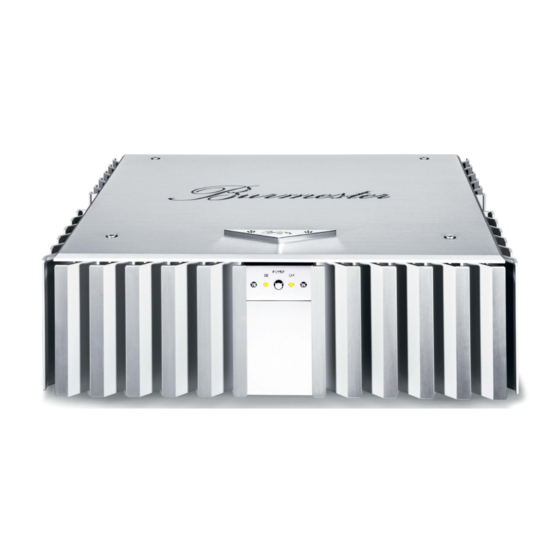
Summary of Contents for Burmester CLASSIC Series
- Page 1 OWNER'S MANUAL 0 3 2 INTEGRATED AMPLIFIER �-�-�;;;;,,. - � �- � �- � ":!}··�· � ✓ • � � �� CLASSIC LINE...
- Page 3 Dear Audiophile, Thank you for choosing this Burmester audio component. We sincerely appreciate your trust in us. You have purchased a unit which excels in musical fidelity and combines uncompromising manufacturing quality with technical innovation and the highest degree of operating flexibility.
-
Page 4: Table Of Contents
C O N T E N T UNPACKING AND SETTING UP FUNCTIONAL OVERWIEW OF FRONT AND REAR PANEL CONNECTIONS OPERATING CONTROLS REMOTE CONTROL THE SETUP MENU ERROR PROTECTION BURLINK GENERAL INSTRUCTIONS TECHNICAL SPECIFICATIONS... -
Page 5: Unpacking And Setting Up
UNPACKING AND SETTING UP CAUTION: The integrated amplifier 032 is very heavy. To avoid injury during unpacking and set-up, this should only be done by persons who are accustomed to handling such weights. The integrated amplifier 032 is shipped inside a plastic protective cover. Make sure that children do not play with it to avoid the danger of suffocation. -
Page 6: Functional Overwiew Of Front And Rear Panel
FUNCTIONAL OVERVIEW FRONT PANEL (1) IR receiver (7) INPUT selector buttons (2) Stand-by LED shows stand-by mode (8) VOLUME knob (9) POWER button for turning the unit on or off (3) Display (4) TONE LED illuminates when tone control is activated (10) TONE button for activating/deactivating the (5) INPUT button for SURROUND input tone control or the tone control setup... -
Page 7: Connections
CONNECTIONS All terminals for hook up are located on the rear panel. While connecting the amplifier all components of the music system must be turned off. CAUTION: Before connecting the unit please check if the input voltage of the 032 is equal to the local voltage of your wall outlet. - Page 8 The pinning of the balanced output is: PIN1=GND, PIN2=NEG, PIN3=POS. Volume and tone control have no influence to the TAPE OUT signal. Connecting DC OUT (25) to the corresponding DC IN-jack of another BURMESTER-unit REMOTE offers to switch on or off this other unit simultaneous by the 032. In this case, 032 has the master function.
-
Page 9: Operating Controls
OPERATING CONTROLS With the exception of the AC mains switch all operating controls are located on the front panel. To operate the unit it must be connected to the AC supply. The AC mains switch (19) which turns AC power to the unit on and off is located on the AC mains switch rear panel above the AC mains terminal. -
Page 10: Remote Control
The tone control allows increasing or decreasing bass and treble output in 2dB steps from Adjusting the plus to minus 14dB and an adjustment of the stereo balance in 1dB steps up to –60dB. tone control Pressing and holding the button labeled TONE (10) switches into the tone control mode. The menu items treble, bass and balance can be called up sequentially by briefly pressing the TONE button. -
Page 11: The Setup Menu
THE SETUP MENU The setup menu allows the easy programming of certain basic settings of the integrated amplifier 032. Press the button SETUP (11) on the front panel or press the MENU button on the remote Activating setup control. The different items of the setup menu are selected in the sequence specified below by Select menu item repeatedly pressing the SETUP or MENU button. -
Page 12: Error Protection
ERROR PROTECTION The integrated amplifier 032 offers a sophisticated error mounting system, which protects the unit as well as the connected loudspeakers from damage, should certain errors occur. If any of the following errors occurs, the loudspeaker relays are automatically switched off and the type of error is indicated in the display (3). -
Page 13: Burlink
BURLINK CONNECTIONS Connecting to the BURLINK interface can be done either with the 9 pin D-SUB connector (RS-232) or with the USB 2.0 connector. RS-232 configuration: 9600Baud, 8bit, parity: none, 1 stop bit, no hardware handshake A USB device driver needs to be installed when using the USB 2.0 connector. System requirements for using the USB software are either WINDOWS 2000 or WINDOWS XP operating system. -
Page 14: General Instructions
Terminals under any circumstances. Static discharges may damage the electronic circuitry inside the unit. The IR receiver (1) receives signals from the BURMESTER remote control and must not be IR receiver covered up by objects. Be careful when touching the housing – it may get quite warm during operation. -
Page 15: Technical Specifications
TECHNICAL SPECIFICATIONS Width x Height x Depth Dimensions 482 x 191 x 482 mm (19.0 x 7.5 x 19.0 inches) approx. 28 kg Weight (approx. 61,7 lbs) for 200V to 240V 50/60Hz Mains voltage and fuses 2 x slow 250mA E, 2 x slow 3,15A E for 100V to 127V 50/60Hz 2 x slow 500mA E, 2 x slow 6,3A E max. - Page 16 Burmester HomeAudio GmbH Wilhelm-Kabus Straße47 • ro829 Berlin, Germany www.burmester.de Version 2.3 2108...


Need help?
Do you have a question about the CLASSIC Series and is the answer not in the manual?
Questions and answers