Advertisement
Quick Links
Advertisement

Related Manuals for XAG P40 Agricultural UAS


Summary of Contents for XAG P40 Agricultural UAS
- Page 1 P40 Agricultural UAS User Manual Version 1.0...
- Page 2 To User Dear user, thank you for choosing XAG products. For safety purposes and better user experience, it is highly recommended that you read this manual carefully and strictly follow the instructions hereof. Contact Us If you have any questions about this document, please contact our Technical Support team via email:...
-
Page 3: Safety Guidelines
Safety Guidelines • Please make sure that the drone operator has passed the drone operation training programme and obtained a drone pilot certificate prescribed by laws and regulations where the product is used in advance. Never operate the drone without permission unless otherwise provided. •... -
Page 4: List Of Items
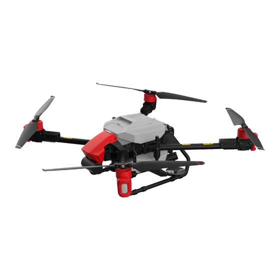
List of Items Please check that the following items are all present when unpacking the box. Should there be any item missed, please contact your dealer. Airframe No.4 Arm No.3 Arm No.2 Arm No.1 Arm ×1 Module Module Module Module ×1 ×1 ×1... - Page 5 About P40 Agricultural UAV The main components of P40 Agricultural UAV are as follows: ① ② ⑱ ③ ④ ⑰ ⑤ ⑥ ⑯ ⑮ ⑦ ⑭ ⑧ ⑬ ⑫ ⑨ ⑪ ⑩ (Above) Figure 1: Airframe Module Structure 1 (Below) Figure 2: Airframe Module Structure 2 ㉔...
- Page 6 Arm No. Arm No. ㉕ ㉖ ㉘ ㉗ Arm No. Arm No. (Below) Figure 3: Airframe Module Structure 3 ① Head Cover ⑪ Peristaltic Pump ㉑ RealTerra System ② PSL Camera ⑫ Landing Gear ㉒ Flight Status Indicator ③ Propeller ⑬...
- Page 7 Airframe Assembly Preparation Remove Spraying Hub Housing Remove Spraying Hub Housing by unscrewing its 6 screws (2 on the top and 2 on both left side and right side ) Remove Central Cabin Cover and Arm Bracket Pull off the Liquid Tank Sensor Cable on the Spraying Hub. Liquid Tank Sensor Cable www.xa.com/en...
- Page 8 Remove 8 Arm Brackets and Central Cabin Cover. www.xa.com/en...
- Page 9 Arms Assembly Put the wire into the Arm. By matching the Arm Position Number to the Airframe Position Number, insert the Arm into the Airframe and fit the Arm Bracket. www.xa.com/en...
- Page 10 Cable Connection Connect ESC Power Cables Upon Arms assembly, push the ESC Power Cables of Arm No.1 & No.2 into the hole of the Bottom Central Compartment and connect to those of arm No.3 & No.4. (The red connector fits only to the other red connector while the black one connects to the other black one).
- Page 11 Tighten connectors on both sides with cable ties upon the connection between Power Cables of Arm No.1 & No.2 in the Bottom Central Compartment. (The red connector fits only to the other red connector while the black one connect to the other black one) Connect Signal Cable of Flight Indicator and Sprayer Pull the Flight Indicator Signal Cables of Arm No.1 and Arm No.2, plus those of the lights and sprayers of Arm No.3 and Arm No.4 through the hole on the Spraying Hub to the Bottom Central Compartment.
- Page 12 Connect Male and Female Connectors of Flight Indicator Before connecting the Flight Indicator Signal Cables, match the Female Connector of Arm No.1 to the Male Connector of Arm No.4 and match the Female Connector of Arm No.2 to the Female Connector of Arm No.3.
Need help?
Do you have a question about the P40 Agricultural UAS and is the answer not in the manual?
Questions and answers