Table of Contents
Advertisement
Advertisement
Table of Contents

Related Manuals for Schiller AT-10 plus


Summary of Contents for Schiller AT-10 plus
- Page 1 AT-10 plus 12-Channel ECG Device Service Handbook...
- Page 2 Sales and Service Information The SCHILLER sales and service centre network is world-wide. For the address of your local distributor, contact your nearest SCHILLER subsidiary. In case of dif- ficulty a complete list of all distributors and subsidiaries is provided on our internet site: http://www.schiller.ch.
-
Page 3: Table Of Contents
AT-10 plus Service Handbook Contents Safety notes ..........7 Responsibility of the user ........... 7 Intended use ................. 7 Organisational measures............. 7 Safety-conscious operation ..........8 Safety facilities ..............8 Operation with other devices ..........8 Safety Symbols and Pictograms ......... 9 1.7.1... - Page 4 AT-10 plus 4.8.1 Battery capacity test................. 25 4.8.2 Print quality and printer alignment check ......... 25 4.8.3 Print quality and printer alignment check patterns ......26 Battery ................. 27 4.9.1 Calibrating the battery..............28 4.10 Software................29 4.10.1 Installing software options..............29 4.10.2 Updating the unit software ...............
- Page 5 AT-10 plus Service Handbook Unit Settings ........... 51 ECG settings ............... 51 Exercise settings ..............56 General and unit settings ..........58 Technical Data ........61 System................. 61 ECG..................62 Safety standards..............63 Construction Drawings ......64 10.1 Exploded views..............64 10.1.1 Base casing..................
- Page 6 AT-10 plus Page 6...
-
Page 7: Safety Notes
Intended use The AT-10 plus is a 12-channel, ECG device used for the recording, analysis and evaluation of ECG Recordings. Recordings made with the AT-10 plus can be used as a diagnostic aid for heart function and heart conditions. The AT-10 plus is designed for indoor use and can be used for all patients of both sexes, all races, and all ages. -
Page 8: Safety-Conscious Operation
– Ruptured fuses must only be replaced with the same type and rating as the orig- inal. Operation with other devices Use only accessories and other parts recommended or supplied by SCHILLER AG. Use of other than recommended or supplied parts may result in injury, inaccurate information and/or damage to the unit. -
Page 9: Safety Symbols And Pictograms
Safety notes AT-10 plus Service Handbook Safety Symbols and Pictograms Safety Symbols and Pictograms 1.7.1 Used symbols in this document The safety level is classified according ANSI Z535.4. The following overview shows the used safety symbols and pictograms used in this manual. -
Page 10: Used Symbols On The Device
• assembly operations, extensions, readjustments, modifications, or repairs are car- ried out by persons authorized by him, and • the SCHILLER AT-10 plus and approved attached equipment is used in accord- ance with the manufacturers instructions. Page 10... -
Page 11: Introduction
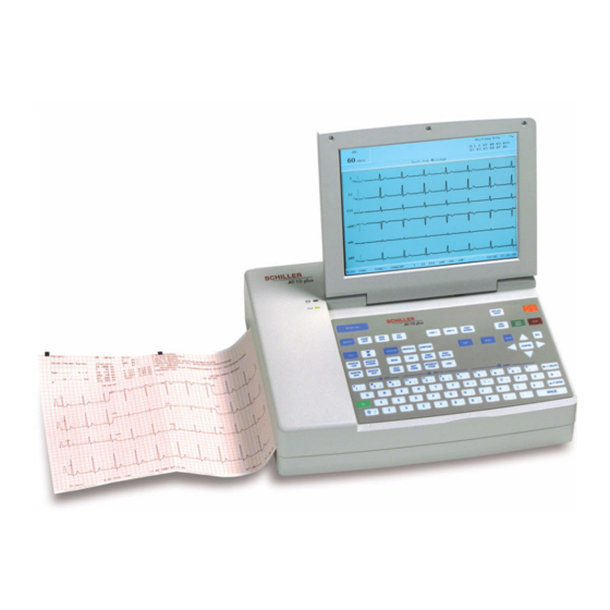
AT-10 plus Service Handbook Features 2 Introduction Features The SCHILLER AT-10 plus is a 12-channel ECG unit designed to record, display, and measure resting ECGs. The AT-10 plus has the following features: 2.1.1 Standard • Pacemaker Detection • Manual (real time) mode - (leads, speed and amplitude can be changed as re- quired) •... -
Page 12: Lcd Screen
Introduction AT-10 plus LCD screen LCD screen The display will vary according to the current task being carried out. In all screens however, the top, middle and bottom areas always display the same information groups. The following is an example of a typical resting ECG screen. -
Page 13: Keypad
Introduction AT-10 plus Service Handbook LCD screen 2.2.1 Keypad The keyboard is divided into the following functional areas: (1) Alphanumeric and Dual Purpose Keys. The numerical keys are dual purpose as follows: – Key 1 - switch myogram filter on or off –... - Page 14 Introduction AT-10 plus LCD screen • Exercise Keys – Exercise key - exercise ECG settings and function – Protocol key - display/select/ edit exercise protocols – Symptoms key - manual input of symptoms – Begin key - start exercise test (beginning of warm-up phase) according to pro- tocol set –...
-
Page 15: External Connections
Use the hospital or building common ground for all mains powered units. If an external printer, monitor or ergo device is connected to the AT-10 plus, the potential equalisation stud must be connected to common ground when the AT- 10 plus is working on battery power i.e.when the mains lead (with grounding lead) -
Page 16: Side Panel
Introduction AT-10 plus External connections 2.3.2 Side panel (1) EKG/ECG patient cable input socket. © • The patient cable and connector is CF rated, that is fully floating and isolated, defibrillation protected, suitable for intra-cardiac application. • The unit is only CF rated and defibrillation protected if used with the original SCHILER patient cable. -
Page 17: Operation Overview
• Do not allow the unit to come into contact with acidic vapours or liquids. • The AT-10 plus should not be placed in the vicinity of X-ray or diathermy units, large transformers or electric motors. It must also be positioned at least one meter from the mains supply. -
Page 18: Switching On And Off
Operation Overview AT-10 plus Start-up and initial preparation 3.1.4 Switching on and off The unit is switched on and off with the On / Off key. 3.1.5 Power supply and battery operation The unit can be operated either from the mains supply or from the built-in rechargeable battery. -
Page 19: Selecting Menu Options Using The Arrow Keys
Operation Overview AT-10 plus Service Handbook Selecting menu options using the arrow keys Selecting menu options using the arrow keys When any of the setting keys are pressed (ECG, Exercise, NIBP, Menu etc.), menu tabs are displayed and menu options displayed, as given in the ECG example below. -
Page 20: Service Screen
Service Screen AT-10 plus 4 Service Screen To enter the service screen press the following key sequence: ‘.’ > ‘.’ > ‘S’ (full stop key pressed twice, followed by ‘s’). A number of tabs at the top of the screen give the following options:... -
Page 21: Nibp
Service Screen AT-10 plus Service Handbook NIBP NIBP Service Character Colour Test Battery Software NIBP Spiro HW-Config. I/O + ports Not available at the time of print. Spiro Service Character Colour Test Battery Software NIBP Spiro HW-Config. I/O + ports Not available at the time of print. -
Page 22: I / O Ports
Service Screen AT-10 plus I / O ports I / O ports Service Character Colour Test Battery Software NIBP Spiro HW-Config. I/O + ports ** RS - 232 test ** Ergo Spiro SpO2 NIPB ** Ergo test out/in ** DC OUT 1 >... -
Page 23: Checking The Analogue Ports
Service Screen AT-10 plus Service Handbook Character 4.5.2 Checking the analogue ports The following ports (on the side panel) can be checked: • DC In • DC Out • ERGO DC In / DC Out Ports Proceed as follows: Using the test cable assembly, connect the DC in and DC out ports together. -
Page 24: Colour
Service Screen AT-10 plus Colour Colour Service Character Colour Test Battery Software NIBP Spiro HW-Config. I/O + ports Palette Cyan In this screen the default background colour can be selected. Choose between: • Cyan • Grey • Blank • Blue To set the background colour proceed as follows: Set the colour. -
Page 25: Battery Capacity Test
If the print quality is not good: – clean the print head with alcohol (see page 50). – check that fresh good quality SCHILLER paper is installed in the unit. – check the electrical / mechanical settings of the print head. -
Page 26: Print Quality And Printer Alignment Check Patterns
Service Screen AT-10 plus Test 4.8.3 Print quality and printer alignment check patterns Print Test Pattern 1 Print Test Pattern 2 Print Test Pattern 3 Print Test Pattern 4 Print Test Pattern 5 Page 26... -
Page 27: Battery
Service Screen AT-10 plus Service Handbook Battery Battery Service Character Colour Test Battery Software NIBP Spiro HW-Config. I/O + ports Discharge Count: Charge Count : Self dis. Count : Saved Energy : 8054 NiMh full value : 5232 Li full value... -
Page 28: Calibrating The Battery
Service Screen AT-10 plus Battery Cal Energy This is the current capacity of the battery and is calculated from: • (Saved energy) - (discharge count) - (self discharge rate) + (charge count) Total Power The ratio of battery capacity to current capacity. This value is used to calculate the battery capacity icon on the display. -
Page 29: Software
All software options are embedded in the unit and can be upgraded with a code. To upgrade an option(s), obtain the option code from SCHILLER, (you will need to state the serial number of the unit (1) to get the code), and proceed as follows: Click the ‘Program Upgrade’... -
Page 30: Updating The Unit Software
Updating the unit software The unit software is updated using a PC program called SWUP. Before updating the unit software, the update program must first be downloaded from the SCHILLER server to a PC. The procedure to update the unit software is a follows: •... -
Page 31: Saving The Settings
Service Screen AT-10 plus Service Handbook Saving the settings 4.11 4.11 Saving the settings All changed settings are remembered until the unit is switched off. If you wish to keep the settings as default, the Menu key must be pressed and software screen must be entered (1), and the ‘save as default‘... -
Page 32: Functional Checks
It is not a full functional test but is intended to provide a general confidence check in all the main functional areas. Comprehensive instructions for operating the unit are provided in the AT-10 plus User Guide. This are available from SCHILLER on request. - Page 33 Functional Checks AT-10 plus Service Handbook General unit integrity check Continuous printout Press the Man Start key to start a continuous printout. Check the printout changes when the following keys are pressed: Lead Group* Sensitivity (Amplitude) Speed To stop the printout, press the Stop key.
-
Page 34: Functional Checks And Tests
Functional Checks AT-10 plus Functional checks and tests Functional checks and tests Required equipment • Safety Tester IEC/EN 60601-1 • Calibrated ECG Patient Simulator (e.g Müller & Sebastiani MS410 ECG Simulator) IMPORTANT! The measurement devices listed above are subject to the instructions according to ISO 9000 in regards to Test Equipment Control. -
Page 35: Mains And Battery Indicators (Led) Test
Functional Checks AT-10 plus Service Handbook Functional checks and tests 5.3.2 Mains and battery indicators (LED) test Connect the power cable at the rear of the unit. – Check that the mains indicator lamp is lit (1) when the unit is connected to the mains supply. -
Page 36: Printer Checks
The paper must stop exactly at the perforation. If this is not the case: – Check that SCHILLER paper is used. – Clean the paper detection opto window with an alcohol solution. – Check the paper mark detection circuit. -
Page 37: Ecg Amplifier And Patient Cable Test
Functional Checks AT-10 plus Service Handbook Functional checks and tests 5.3.8 ECG amplifier and patient cable test With a patient simulator connected, press the ECG key . The electrode Service Character Colour Printer Key Battery Softwar screen is displayed (this screen is also displayed in the service screen (see page... -
Page 38: Ecg Printout Reference
Functional Checks AT-10 plus Functional checks and tests 5.3.11 ECG printout reference Required Equipment • Calibrated test ECG Patient Simulator (e.g Müller & Sebastiani MS410 ECG Sim- ulator) Connect the simulator to the unit and select the calibrated ECG reference wave- form EN 60601-2-51 >... - Page 39 Functional Checks AT-10 plus Service Handbook Functional checks and tests Reference Printout Page 39...
-
Page 40: Language, Date And Time
Functional Checks AT-10 plus Functional checks and tests 5.3.12 Language, date and time System Menu RS-232 Network Modem Peripherals Identification Macro System Config. Software Press the Menu key Select the System tab. Check and select language and press the confirm key... -
Page 41: Safety Tests
Functional Checks AT-10 plus Service Handbook Safety tests Safety tests Bender Safety Tester (recommended) HA2000D High voltage measuring unit (recommended) The safety test is carried out in accordance with the EN 60601-1, Clause 18 and 19. This test may only be carried out with a tester that fulfils the above mentioned norms and has been calibrated in accordance with ISO norms. -
Page 42: Replacing Major Components
Replacing Major Components AT-10 plus Safety notes 6 Replacing Major Components Safety notes Danger of electrical shock. When working on a open device connect the device via an isolation transformer. Follow the procedures for the prevention of accidents and environmental protection according your national guidelines. -
Page 43: Battery Disposal
Replacing Major Components AT-10 plus Service Handbook Changing the fuse and mains voltage 6.2.2 Battery disposal Danger of explosion. Battery may not be burned or disposed of domestic refuse. Danger of acid burns! Do not open the battery. The battery is to be disposed of in municipally approved areas or sent back to SCHILLER AG. -
Page 44: Opening The Case
Before commencing any removal or replacement procedures ensure that the mains power supply is switched off and that the mains cable is removed. • The AT-10 plus contains static sensitive CMOS components; observe antistatic precautions: • When carrying out any maintenance procedures always place the unit on an earthed antistatic mat. - Page 45 Replacing Major Components AT-10 plus Service Handbook Opening the case Gently lift the Top Assembly sufficiently to gain access to the interconnecting cables. Disconnect the cable assembly between the main board and the printer (two cable assemblies) and the power cable between the main board and the battery.
-
Page 46: Printer
Loosen the screw for the ground cable. Thermal paper handling The thermal paper used in the AT-10 plus requires slightly different handling to normal paper as it can react with chemicals and to heat. However, when the following points are remembered, the paper will give reliable results: The following points apply to both storage, and when archiving the results. -
Page 47: Communication Module
Replacing Major Components AT-10 plus Service Handbook Opening the case 6.4.3 Communication module The complete electronic assembly must be removed to remove the communica- tion module. Remove the recessed screws securing the assembly to the casing. Gently lift the assembly away from the casing and remove connectors. - Page 48 Replacing Major Components AT-10 plus Opening the case Remove the two connector screws. Remove the board. Page 48...
-
Page 49: Reassembling The Unit
Replacing Major Components AT-10 plus Service Handbook Reassembling the unit Reassembling the unit 6.5.1 Internal sight control If the device has been opened, the device must be given a full sight control before it is screwed back together. Check following items: •... -
Page 50: Cleaning
The casing of the AT-10 plus can be cleaned with a soft damp cloth on the surface only. Where necessary a domestic non-caustic cleaner can be used for grease and finger marks. -
Page 51: Unit Settings
Unit Settings AT-10 plus Service Handbook ECG settings 8 Unit Settings Menu navigation, selection and confirmation is detailed in the Introduction, see page All changed settings are remembered until the unit is switched off. If you wish to keep the settings as default, the ‘save as default‘ icon (Menu key > Software > Save as Default), must be pressed before switch off - see page 31. - Page 52 Unit Settings AT-10 plus ECG settings Parameter Options Description Interpretation Interpretation Screen Edit/ Enter interpretation. Write Unconfirmed Report Yes or No. ‘Unconfirmed Report‘ is added/not added to the interpretation state- ments on the auto ECG printout (if applicable). Write Abnormal ECG Yes or No.
- Page 53 Unit Settings AT-10 plus Service Handbook ECG settings Parameter Options Description Autom. Format ECG Printout No Printout No printout of the ECG given at the end of an auto mode (Automatic mode for recording (the recording can be stored in the memory formats 1 and 2) and printed at a later time if required).
- Page 54 (off). The cutoff frequency is set above. SSF Filter (smoothing) The smoothing filter (SSF: SCHILLER smoothing filter) is a low pass filter to suppress high frequency artefacts between the QRS complexes. When this filter is switched on, `SSF` is shown on the bottom line of the automatic printout.
-
Page 55: Exercise Settings
Unit Settings AT-10 plus Service Handbook Exercise settings Exercise settings When the Exercise key is pressed a screen is shown with a number of tabs at the top. When the tabs are selected further exercise options and settings are available. This section gives an overview of all the settings and tabs available in the following table. - Page 56 Unit Settings AT-10 plus Exercise settings Parameter Options Description Final Report ST Trends A graph of the ST amplitude and slope. Select Yes to print, or No to suppress printing. ST-HR Diagram (not A graph of the ST amplitude against heart rate. Select Yes to print, or No to available at time of print) suppress printing.
-
Page 57: General And Unit Settings
Unit Settings AT-10 plus Service Handbook General and unit settings General and unit settings When the Menu key is pressed a screen is shown with a number of tabs at the top. When the tabs are selected system and general options and settings are available. - Page 58 Parameter Options Description Software The current software version for the AT-10 plus. Also displayed is the serial Software Version Display number of the unit and any options that are installed as follows: Base configuration (upper case) M = Measurements (Standard)
- Page 59 Unit Settings AT-10 plus Service Handbook General and unit settings Parameter Options Description Modem At the time Phone Number Enter the telephone number preceded by `T` or `P` (tone or pulse). of print this function was not fully A comma `,` gives a one second pause in dialling - this may be necessary for defined.
-
Page 60: Technical Data
Technical Data AT-10 plus System 9 Technical Data System Dimensions 348 x 288 x 87 mm, approx. 4.2 kg. Monitor • Backlit for graphic and LCD alphanumeric representation • Resolution: 800 x 600 dots Power supply Mains Voltage • 220 - 240 V (nominal), 50 / 60 Hz; 100 - 115 V (nominal), 50 / 60 Hz;... -
Page 61: Ecg
Technical Data AT-10 plus Service Handbook Patient input Fully floating and isolated, defibrillation-protected (only with original SCHILLER pa- tient cable) Leads • 12 simultaneous leads • Standard • Cabrera Monitor display Leads • 3 - 12 channel display of the selected leads –... -
Page 62: Safety Standards
Technical Data AT-10 plus Safety standards Safety standards Safety standard IEC/EN 60601-1 IEC/EN 60601-2-25 IEC/EN 60601-1-2 Protection class I according to IEC/EN 60601-1 (with internal power supply) Conformity/Classification CE/IIa according Directive 93/42/EEC Safety class CF according to IEC 601-1, IEC 601-2-25, CSA, UL; IIb according to MDD 93/42/... -
Page 63: 10 Construction Drawings
Construction Drawings AT-10 plus Service Handbook Exploded views 10.1 10 Construction Drawings 10.1 Exploded views 10.1.1 Base casing Paper mark detector MK 17-4 Thermal Printer Paper tray DC motor Part No 4.330036 Paper Tray Battery Charge Print MK 22-5 Battery Pack Part No. -
Page 64: Top And Lcd Casing
Construction Drawings AT-10 plus 10.1 Exploded views 10.1.2 Top and LCD casing Part No 4.416126 Keyboard Foil Part No. 4.450331 Communication Module AC/DC Converter Shield Part no. 4.416115 ECG Print MK 22-2 Shield Part No. 4.416118 DC/DC Converter Shield Part No. -
Page 65: Circuit And Functional Illustrations
Construction Drawings AT-10 plus Service Handbook Circuit and functional illustrations 10.2 10.2 Circuit and functional illustrations The circuit diagrams are confidential. Therefore only the high level drawings are provided here. 10.2.1 Connection block diagram MAINS INPUT 2 x 200mAT (230VAC / 50HZ) -
Page 66: Microprocessor (Main Board) Functional Block Diagram
Construction Drawings AT-10 plus 10.2 Circuit and functional illustrations 10.2.2 Microprocessor (main board) functional block diagram Page 66... -
Page 67: Communication Module Functional Block Diagram
Construction Drawings AT-10 plus Service Handbook Circuit and functional illustrations 10.2 10.2.3 Communication module functional block diagram Sheet 12 Sheet 8 Sheet 7 Power-Clock and Interface.SCH Quad UART.SCH Modem .SCH ETHSTAT ETHSTAT SCMRESET/ INTMODEM/ SCMRESET/ SCMRESET/ RTSUART2 CLK12 RTSUART2 CLK12... -
Page 68: Ecg Amplifier Functional Block Diagram
Construction Drawings AT-10 plus 10.2 Circuit and functional illustrations 10.2.4 ECG amplifier functional block diagram P23B WANNE-10-2 +5.2V EKG-INTERFACE EKG-INTERFACE.SCH PART_C KAN1_2 EKGRES PART_C.SCH KAN1_2.SCH RA-F EKGRES RA-F C1OS LA-F RLOS C1OS LA-F C1-F PM/E C1-F PM/E PM/E C1-F C2-F... -
Page 69: Main (Microprocessor) Board Component Layout
Construction Drawings AT-10 plus Service Handbook Circuit and functional illustrations 10.2 10.2.5 Main (microprocessor) board component layout Page 69... -
Page 70: Ecg Board Component Layout
Construction Drawings AT-10 plus 10.2 Circuit and functional illustrations 10.2.6 ECG board component layout Page 70... -
Page 71: Communication Module Component Layout
Construction Drawings AT-10 plus Service Handbook Circuit and functional illustrations 10.2 10.2.7 Communication module component layout Page 71... -
Page 72: 11 Special Test Equipment
Special Test Equipment AT-10 plus 11.1 RS test plug 11 Special Test Equipment The following test plugs and equipment must be fabricated to carry out the interface tests (see page 24). 11.1 RS test plug Using an RS plug, solder together pins 2 and 3. -
Page 73: 12 Checklist
AT-10plus checklist table 12.1 12 Checklist The following procedural checklist must be carried out by authorised SCHILLER trained personnel. The recommended interval is that the unit is checked every 12 months. It is a requirement of EN 60601 that the unit undergoes a safety test at least every 12 months (see page 41), and a complete functional check at least every 24 months (detailed in the following checklist). - Page 74 Checklist AT-10 plus 12.1 AT-10plus checklist table Reference False Remark 4.8.2 Print quality and printer alignment check (page 25) No fading Alignment OK No faulty pixels Blackness, regularity and good readability on the complete print width Paper Feed (page 36)
- Page 75 Checklist AT-10 plus Service Handbook AT-10plus checklist table 12.1 Reference False Remark 5.3.12 Language, date and time (page 40) Set Language. Set Time. Set Date. 5.3.13 External monitor (page 40) Connect external monitor - monitor displays the same data as the integral LCD.
- Page 76 Checklist AT-10 plus 12.1 AT-10plus checklist table Other remarks Page 76...
Need help?
Do you have a question about the AT-10 plus and is the answer not in the manual?
Questions and answers
uma impressora externa para impressão na folha A4