Table of Contents
Advertisement
Quick Links
Advertisement
Table of Contents

Related Manuals for Schiller AT-101


Summary of Contents for Schiller AT-101
- Page 1 A"-$0$ A"-$0$ $7-=>annel E=G Devi+e &ervi+e -andboo3...
- Page 2 Sales and Service Information The SCHILLER sales and service centre network is world-wide. For the address of your local distributor, contact your nearest SCHILLER subsidiary. In case of dif- ficulty a complete list of all distributors and subsidiaries is provided on our internet site: http://www.schiller.ch.
-
Page 3: Table Of Contents
Standard Features ................9 2.1.2 Optional Features................9 2.1.3 Initiating Functions or Tasks .............. 9 2.1.4 Main Components of the AT-101 ............. 10 2.1.5 Back Panel ..................10 Keypad................. 11 LCD Screen ................. 13 Operation ..........14 Start-up and Initial Preparation ......... 14 3.1.1... - Page 4 4.4.1 Print Setup ..................28 4.4.2 Communications Test ..............28 Software................29 4.5.1 Preparing serial communication for software update....... 29 4.5.2 Update software ................30 4.5.3 Upgrade to a new option..............31 4.5.4 Default Settings................32 Care Z Maintenance .......33 Service Interval ..............
- Page 5 A"#$0$ Service Handbook 7.1.2 AT-101 pictures................55 Electrical drawing ............... 57 7.2.1 Power supply..................57 7.2.2 Component layout ................58 Appendix ..........59 Checklist................59 Index ............63 Page 3...
- Page 6 Page 4...
-
Page 7: Safety Notes
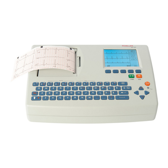
Intended use ! The AT-101 is a 12-channel, ECG device used for the recording, analysis and evaluation of ECG Recordings. Recordings made with the AT-101 can be used as a diagnostic aid for heart function and heart conditions. The AT-101 is de- signed for indoor use and can be used for all patients of both sexes, all races, and all ages. -
Page 8: Safety-Conscious Operation
– Ruptured fuses must only be replaced with the same type and rating as the orig- inal. Operation with other devices ! Use only accessories and other parts recommended or supplied by SCHILLER AG. Use of other than recommended or supplied parts may result in injury, inac- curate information and/or damage to the unit. -
Page 9: Safety Symbols And Pictograms
Safety notes A"#$0$ Service Handbook Safety Symbols and Pictograms Safety Symbols and Pictograms 1.7.1 Used symbols in this document The safety level is classified according ANSI Z535.4. The following overview shows the used safety symbols and pictograms used in this manual. For a direct danger which could lead to severe personal injury or to death. -
Page 10: Used Symbols On The Device
Attention: Consult accompanying documents. Terms of Warranty The SCHILLER AT-101 is warranted against defects in material and manufacture for the duration of one year (as from date of purchase). Excluded from this guarantee is damage caused by an accident or as a result of improper handling. The warranty en- titles free replacement of the defective part. -
Page 11: Introduction
2 Introduction Features The SCHILLER AT-101 is a 12-channel ECG unit designed to record, display, and an- alyse resting ECGs. The unit has been extensively researched to give an ergonomic, clear interface thatks easy to use without compromising functionality. The AT-101 has the following features: 2.1.1... -
Page 12: Main Components Of The At-101
2.1.5 Back Panel ! All externally connected hardware must be approved by SCHILLER. Connection of any hardware not approved by SCHILLER is at the ownerks risk. The unit guar- antee may also be invalid. See also safety note paragraph 1.6. -
Page 13: Keypad
Introduction A"#$0$ Service Handbook Keypad Keypad 78 / min Filter on LEAD MANUAL MENU TEST PRINT (1) Softkeys - the function of these keys changes depending on the screen dis- played. The function of these keys is shown on the screen above the keys. If nothing is written above a softkey, it has no function for the current screen. - Page 14 Introduction A"#$0$ Keypad (4) The top figures on the number keys k1kand k2k(designated < and >), change the lead group displayed on the screen, forward and backward resp. (5) Auto sensitivity key - automatically sets the ECG printout sensitivity (in AUTO mode only) to the best setting for the signal strength (5mm/mV or 10mm/mV) (6) The top figures on the number keys designated 5, 10, and 20 set the sensitivity of the ECG both on the screen and on the (manual) printout.
-
Page 15: Lcd Screen
Introduction A"#$0$ Service Handbook LCD Screen LCD Screen The display will vary according to the current task being carried out. In all screens however, the top and bottom lines always display the same information: the top line displays system information, and the bottom line always gives the softkey options. The following is an example of a typical resting ECG screen. -
Page 16: Operation
If the unit is switched on, the relevant symbol is displayed on the LCD (7) Leave the AT-101 connected to the mains for 7 hours to fully charge the battery. Connect the potential equalisation cable and all other necessary cables at the rear of the AT-101. -
Page 17: Battery Operation
The potential equalisation stud (see Fig. Fig. 3.1) at the rear of the unit can be used to equalise the ground potential of the AT-101 to that of all mains powered equipment in the vicinity. Use the hospital or building common ground... -
Page 18: Entering The Setup Menu
Operation A"#$0$ Entering the SETUP Menu Entering the SETUP Menu To enter the setup screen press the following keys. MENU Press the softkey MENU. Press the function key FN and the softkey SETUP. Note: MEMORY SETUP REST The Setup text above the key appears first if the FN key is pressed. SETUP 3.2.1 Navigating in the Setup Screens... -
Page 19: Ecg Settings
Operation A"#$0$ Service Handbook ECG Settings ECG Settings Press the softkey MENU. MENU Press the function key FN and the softkey SETUP. Note: MEMORY SETUP REST The Setup text above the key appears first if the FN key is pressed. SETUP Press the softkey ECG SETTINGS. -
Page 20: Automatic Format 1 And 2 Internal Printer
Operation A"#$0$ ECG Settings 3.3.1 Automatic Format 1 and 2 Internal Printer Two separate Auto formats can be defined for the internal printer. NEXT General Lead Interpretation Filter Auto. Format 2 external Auto. Format 1 external Auto Format 2 internal external Automatic Format 1 internal... -
Page 21: Automatic Format 1 And 2 External Printer
Operation A"#$0$ Service Handbook ECG Settings 3.3.2 Automatic Format 1 and 2 External Printer Two separate Auto formats can be defined for a external printer. NEXT General Lead Interpretation Filter Auto. Format 2 external Auto. Format 1 external external Auto Format 2 internal Automatic Format 1 internal Press the SELECT softkey to choose from the following options:... -
Page 22: Filters
The Baseline Stabiliser is applied to a recording (on), or not applied to a recording (off). The smoothing filter (SSF: SCHILLER smoothing filter) is a low pass filter Smoothing Filter to suppress high frequency artefacts between the QRS complexes. When... -
Page 23: Interpretation (Only With Version C)
Operation A"#$0$ Service Handbook ECG Settings 3.3.4 Interpretation (Only with version C) The interpretation settings enable the user to determine whether or not certain com- ments will be added to the interpretation statements on the ECG printout. Further- NEXT more, the patient’s age can be assumed (<30 or >30). Low or high can also be set for General interpretation sensitivity. -
Page 24: Leads
Operation A"#$0$ General (only with version m = Memory) 3.3.5 Leads Defining Lead Sequence Z Printout The required settings can be selected as follows: NEXT General Lead Interpretation Filter Auto. Format 2 external Auto. Format 1 external Auto Format 2 internal external Automatic Format 1 internal... -
Page 25: System Settings
TEST UNIT COMM EXIT AND INFO The following pages detail system settings for the AT-101: " Use the SELECT softkey (1) to select the different settings " Use the UP/DOWN softkeys (2) to highlight the various options. UNIT User ID... -
Page 26: Unit
System Settings A"#$0$ Unit Unit " Press softkey UNIT TEST UNIT COMM EXIT AND INFO Parameter Options Description The user identification is printed on all recordings. The user ID can be User Identification (User ID) the department, doctor or hospital etc. Select User ID and a blinking cur- sor is present - enter up to 30 characters via the keypad. -
Page 27: Communication
System Settings A"#$0$ Service Handbook Communication Communication " Press softkey COMM TEST UNIT COMM EXIT AND INFO Parameter Options Description Select a Baud rate according to the modem/computer used. Most comput- 9600 Baudrate ers can connect at 115200 Baud and the standard modem speed is 57600 14400 Baud. -
Page 28: Setup Transmitting
– stop bit - 2 – time between blocks, records - 100ms " Check that the transmission speed is the same in both the AT-101 and the SEMA- COMM program. The transmission settings are defined in Setup and are described in paragraph 4.3. -
Page 29: Test And Information
A code of the options installed is given after the software version. These are as fol- lows: AT-101 Basic configuration V1.0 Ctm RI5.73 070.1234567 26.09.2003 = Measurement Copyright } 2002-03 = Measurement and Interpretation SCHILLER AG, Switzerland Optional configuration PRINT COMM BASE EXIT SOFTWARE SETUP TEST INIT. = Memory... -
Page 30: Print Setup
System Settings A"#$0$ Test and Information 4.4.1 Print Setup " To obtain a printout press the PRINT SETUP softkey. A printout of the defined settings will be produced and gives the following information, PRINT COMM BASE EXIT SOFTWARE SETUP TEST INIT. -
Page 31: Software
Preparing serial communication for software update • Requirement to run Install.exe file: Win NT4, Win 98, Win 2000, Win XP. • Connect the AT-101 to the mains • Do not power off during update! • RS-232 cable • Download software Install•AT101xxx.exe Connect the RS-232 cable to the connector (1) on the back of the device. -
Page 32: Update Software
Press the button “Download” on the dialogue box of your PC. Fig. 4.2 Software dialogue box The bargraph shows the progress of the download. After downloading, the device will restart automatically. Check the Software version in the menu TEST and INFO. AT-101 1.01 CANCEL Page 30... -
Page 33: Upgrade To A New Option
Upgrade to a new option Use the upgrade function to activate any available software options (e.g. Measure- ment). To activate new options in the AT-101, a code must be entered. This code must be obtained from SCHILLER. To install software option proceed as follows: Enter the TEST and INFO screen SETUP >... -
Page 34: Default Settings
System Settings A"#$0$ Software 4.5.4 Default Settings To reset the unit to the base default settings, press the BASE INIT softkey. As the unit resets to the default values a message is briefly displayed on the LCD. The base set- PRINT COMM BASE... -
Page 35: Care Z Maintenance
Maintenance work not described in this chapter, e.g. battery changes, may only be accomplished by a qualified technician authorised by SCHILLER AG. The following table gives information about interval and competence of maintenance which can be required. -
Page 36: Functional Test
Care & Maintenance A"#$0$ Functional test Functional test Opening of the Device Whenever a device is opened for repairs or calibration, a functional and Safety Test has to be carried out at the end of the operation. Required Measurement Equipment •... -
Page 37: Mains Indicator Led Test
Care & Maintenance A"#$0$ Service Handbook Functional test 5.2.3 Mains indicator LED test Connect the power cable at the rear of the unit. • The mains indicator lamp (6) is always lit when the unit is connected to the mains supply. -
Page 38: Paper Feed
Care & Maintenance A"#$0$ Functional test 5.2.7 Paper Feed Start printer with "MAN PRINT". Press the key twice. The paper has to stop exactly at the perforation. If this is not the case, control the paper mark comparison. 5.2.8 Printer quality test Go to the menu "LEAD TEST"... -
Page 39: Parallelism Test
Care & Maintenance A"#$0$ Service Handbook Functional test 5.2.10 Parallelism test This will test the mechanical adjustment of the print head to the paper grids. Start the manual printout. Press the "1 mV" key. Stop printout and check the parallelism of the print to the paper grid. –... -
Page 40: Ecg Lead And Patient Cable Test
Care & Maintenance A"#$0$ Functional test 5.2.12 ECG lead and patient cable test Press “FN” key and Lead test. Disconnect ECG simulator. ECG AMPLIFIER: U el [mV] Check following: Uref+: 2002 -517 Uref-: 2000 -518 – device beeps 4 time Udif: 4001 -520... - Page 41 Care & Maintenance A"#$0$ Service Handbook Functional test ECG leads printout This printout can be used on a transparency foil to compare your printout. Be sure that no Zoom is used for a print on a transparency foil. Page 39...
- Page 42 Care & Maintenance A"#$0$ Functional test Page 40...
-
Page 43: External Printer Test
TEST Fig. 5.6 5.2.14 Communication (RS-232) Test This test uses a special test plug (DB9 Pin 2 and 3 bridged) to check transmission line and connector to ensure that the AT-101 transmission circuits are functioning. TEST UNIT COMM EXIT AND INFO Connect RS-232 loop test connector at the RS-232 port. -
Page 44: Safety Tests
Care & Maintenance A"#$0$ Safety Tests Safety Tests The safety test is carried out in accordance with the EN 60601-1, Clause 18 and 19. This test may only be carried out with a tester that fulfils the above mentioned norms and has been calibrated in accordance with ISO norms. -
Page 45: Maintenance Interval For The Battery
Care & Maintenance A"#$0$ Service Handbook Maintenance interval for the battery Maintenance interval for the battery Important The battery is maintenance free during its normal life. The battery should remain charged during storage. If the storage period exceeds three months, recharge the battery. •... -
Page 46: Replacing Battery
! Danger of explosion! Battery may not be burned or disposed of domestic refuse. ! Danger of acid burns! Do not open the battery. The battery is to be disposed of in municipally approved areas or sent back to SCHILLER AG. Page 44... -
Page 47: Changing The Fuse And Mains Voltage
Care & Maintenance A"#$0$ Service Handbook Changing the fuse and mains voltage Changing the fuse and mains voltage ! The mains voltage may only be changed by qualified personnel. ! Before the fuse and mains voltage are changed, the device must be disconnected from the mains and remove the mains plug. -
Page 48: Cleaning
The casing of the AT-101 can be cleaned with a soft damp cloth on the surface only. Where necessary a domestic non-caustic cleaner can be used for grease and finger marks. -
Page 49: Printer
5.7.2 Thermal Paper Handling The thermal paper used in the AT-101 requires slightly different handling to normal paper as it can react with chemicals and to heat. However, when the following points are remembered, the paper will give reliable results: The following points apply to both storage, and when archiving the results. -
Page 50: Replacing Printer
Care & Maintenance A"#$0$ Printer 5.7.3 Replacing Printer Disconnecting device from the mains. Loosen the 6 Phillips screw from the back housing. Remove the cover. Open the Printer and remove the paper. Loosen the four Phillips screws (1). Loosen the screw for the ground cable Unplug Printer cable 3 and 4. -
Page 51: Fault-Finding
" Press the OFF key. Wait a few seconds and switch on again. • Mains supply ok, but the screen is " If the screen is still not lit: Call your local SCHILLER rep- still not lit resentative. • Wrong settings "... -
Page 52: Accessories And Disposables
Your local representative stocks all the disposables and accessories available for the AT-101. A full list of all SCHILLER representatives can be found on the SCHILLER website (www.schiller.ch). In case of difficulty contact our head office. Our staff will be pleased to help process your order or to provide any details for all SCHILLER products. -
Page 53: Technical Data
Technical Data A"#$0$ Service Handbook System 6 Technical Data System Dimensions 290x 198 x 76 mm, approx. 2.6 kg Built-in monitor 76 x 57 mm effective display area, 320 x 240 dots resolution Power supply • 220 - 240 V (nominal), 50 / 60 Hz; 110 - 115 V (nominal), 50 / 60 Hz; Mains Voltage •... -
Page 54: Technical Data For Ecg
Technical Data A"#$0$ Technical Data for ECG Technical Data for ECG Patient input circuit Fully floating and isolated, defibrillation-protected (only with original SCHILLER patient cable) Leads • 12 simultaneous leads • Standard • Cabrera Monitor display • 3-channel display of the selected leads Leads –... -
Page 55: Safety Standards
Technical Data A"#$0$ Service Handbook Safety Standards Safety Standards Safety standard IEC/EN 60601-1 IEC/EN 60601-2-25 IEC/EN 60601-1-2 Protection class I according to IEC/EN 60601-1 (with internal power supply) Conformity/Classification CE/IIa according Directive 93/42/EEC Protection This device is not designed for outdoor use (IP 20) Page 53... -
Page 56: Drawing And Spare Parts
Drawing and spare parts A"#$0$ Drawings Printer 7 Drawing and spare parts Drawings Printer 3x SK M3x6 Thermal printer 3.920907 Fig. 7.1 Drawing printer 7.1.1 Flap and Drive roll Fig. 7.2 Drawing flap and drive roll Page 54... -
Page 57: At-101 Pictures
Drawing and spare parts A"#$0$ Service Handbook Drawings Printer 7.1.2 AT-101 pictures Fig. 7.3 AT-101 open top view Page 55... - Page 58 Drawing and spare parts A"#$0$ Drawings Printer Fig. 7.4 Detail cabling Page 56...
-
Page 59: Electrical Drawing
Drawing and spare parts A"#$0$ Service Handbook Electrical drawing Electrical drawing The electrical drawing are confidental. Therefore just the most important drawing or parts of drawing are printed here. 7.2.1 Power supply Page 57... -
Page 60: Component Layout
Drawing and spare parts A"#$0$ Electrical drawing 7.2.2 Component layout SI 1 R470 R485 R465 Page 58... -
Page 61: Appendix
Appendix A"#$0$ Service Handbook Checklist 8 Appendix Checklist Name of tester: Visa: Device serial number: Software Version: Customer: Date: Reference/Testpoints False Remark 5.2.1 Internal Sight Control page 34 Plugs are properly in the socket and secured All protective cable (green/yellow) are properly laid out and securely con- nected to one the earth point (potential equalisation). - Page 62 Appendix A"#$0$ Checklist Reference/Testpoints False Remark The mains indicator lamp (6) switches off and the symbol battery is dis- played on the LCD (7). 5.2.7 Paper Feed page 36 The paper has to stop exactly at the perforation. If this is not the case, con- trol the paper mark comparison.
- Page 63 Appendix A"#$0$ Service Handbook Checklist Other remarks Page 61...
- Page 64 Appendix A"#$0$ Checklist Page 62...
-
Page 65: Index
Communication ........ 25 screen contrast......15, 35 Communications Test ...... 28 Select desired parameters....16 Confirm the setting ......16 Sensitivity..........21 Connecting AT-101 ......14 Signals ..........22 Smoothing Filter........20 Date and Time ......... 24 Softkeys ..........11 Default Settings........ 32 software update ........29 Download software ...... - Page 66 Index A"#$0$ Page 64...
Need help?
Do you have a question about the AT-101 and is the answer not in the manual?
Questions and answers