Table of Contents
Advertisement
Quick Links
Advertisement
Table of Contents

Subscribe to Our Youtube Channel
Related Manuals for Schiller AT-102


Summary of Contents for Schiller AT-102
- Page 1 AT-102 ECG Recorder Service Handbook Contents AT-102 12-Channel ECG Recorder Service Handbook SCHILLER AG Altgasse 68 6341 Baar, Switzerland Phone: + 41 41 766 42 42 Fax: + 41 41 761 08 80 www.schiller.ch Article Number 2. 540 028 SCHILLER AG 2002...
- Page 2 Physicians Guide to the SCHILLER Interpretation and Measurement Program AT-102 User Guide The SCHILLER sales and service centre network is worldwide. For the address of your local distributor, contact your nearest SCHILLER subsidiary. In case of difficulty a complete list of all distributors and subsidiaries is provided on our internet site: http://www.schiller.ch...
-
Page 3: Intended Use
The AT-102 is a 12-channel ECG device used for the recording, analysis and evaluation of ECG Recordings. Recordings made with the AT-102 can be used as a diagnostic aid for heart function and heart conditions. The AT-102 is designed for indoor use and can be used for all patients of both sexes, all races, and all ages. -
Page 4: Table Of Contents
Section 1 Operating Elements ......1.1 Introduction .................. 1.2 Features .......................1.2 Operating Philosophy Overview ...............1.3 Initiating Functions or Tasks ..............1.3 Main Components of the AT-102 ..............1.4 Back Panel ....................1.5 Power Supply ....................1.6 Switching On and Off .................1.6 Changing a Mains Fuse ................1.7 Potential Equalisation ................1.7... - Page 5 AT-102 ECG Recorder Service Handbook Contents ECG Settings ................1.12 Auto Format 1 and 2 ................1.13 ECG Printout .................... 1.13 Average Cycles ..................1.14 Rhythm Leads ..................1.14 Measurements, Markings and Interpretation ........1.14 Filters ......................1.15 Baseline filter .................... 1.15 Myogram filter ..................
- Page 6 AT-102 Fault Diagnosis Chart (Sheet C - General Problems) ....3.7 AT-102 Fault Diagnosis Chart (Sheet D - Printer Problems)....3.8 AT-102 Fault Diagnosis Chart (Sheet F - Exercise Mode Problems) ..3.9 AT-102 Fault Diagnosis Chart (Sheet G - Spirometry Problems) ..3.10 AT-102 Fault Diagnosis Chart (Sheet H - Communication (RS) Problems) ..................
- Page 7 AT-102 ECG Recorder Service Handbook Contents Functional Check ................ 3.12 Thermal Printer Check..............3.13 Print Head Alignment and Print Head Tension........3.14 Thermal Printer Fault Diagnosis ............. 3.14 RS-232 Interface (and Spiro Check) .......... 3.15 Section 4 Module Removal and Replacement .. 4.1 Introduction ..................
- Page 8 SCHILLER AT-102 ECG Recorder Service Handbook Section 5 Adjustments, System Upgrades and Software Updates ..........5.1 Introduction .................. 5.3 Safety Notices and Conditions ............. 5.4 Conditions ....................5.4 Test Equipment ................5.5 Proprietary Test Equipment/Tools ............5.5 Main Board MK 14-10 Adjustment Locations ....... 5.6 Component Location MK18-1 (Component Side) ........5.6...
- Page 9 Technical Data for ECG: ................7.4 Technical Data for Spirometry (Option): ...........7.5 Standard ......................7.7 Configurations ....................7.7 Annex A Glossary..........A.1 Introduction ................. A.2 Acronyms ..................A.3 Annex B AT-102 Circuit Diagrams and Engineering Drawings ........B.1 Index Article Number 2. 540 028 SCHILLER AG 2002...
-
Page 10: Terms Of Warranty
SCHILLER AT-102 and approved attached equipment is used in accordance with the manufacturers instructions. THERE ARE NO EXPRESS OR IMPLIED WARRANTIES WHICH EXTEND BEYOND THE WARRANTIES HEREINABOVE SET FORTH. -
Page 11: Disposal Instructions And Battery Care
Alternatively, used batteries and components can be returned to SCHILLER AG for disposal. Units no longer required can be returned to SCHILLER AG for disposal. Alternatively dispose of the unit in municipally approved recycling centres. Article Number 2. 540 028... -
Page 12: Safety Notices
The guidelines for patient electrode placement are provided as an overview only. They are not a substitute for medical expertise. IEC 601-1-1 states that the patient must remain at least 1.5 metres clear of the AT-102. When this is not possible an isolation transformer must be installed. -
Page 13: Precautions For Operation With Other Devices
In case of doubt, the patient should be disconnected from the recorder. To avoid possible interference from the Ergometer when carrying out an exercise test, it is recommended that both the AT-102 and the Ergometer are connected to the same common ground. xiii Article Number 2. -
Page 14: Maintenance Precautions
SCHILLER AT-102 ECG Recorder Service Handbook Safety Notices Maintenance Precautions BEFORE CARRYING OUT ANY MAINTENANCE PROCEDURES, SWITCH THE UNIT OFF AND DISCONNECT FROM THE MAINS BY REMOVING THE MAINS PLUG. The unit is protected by double pole / neutral fusing for continued protection against the risk of fire. -
Page 15: Symbols And Conventions Used In This Service Handbook
AT-102 ECG Recorder Service Handbook Contents Symbols and Conventions Used in this Service handbook The following words and symbols mark special messages throughout this guide. General Warning. Text set off in this manner indicates that failure to follow directions could result in bodily harm or loss of life or failure to follow directions could result in damage to equipment or loss of information. -
Page 16: What's In This Book
AT-102 ECG Recorder Service Handbook What's in this book The service philosophy for the AT-102 is fault finding to module level. The purpose of this book is to provide all the information necessary to enable the service engineer to efficiently locate and replace a faulty module. - Page 17 The full technical specification of the AT-102 is given in this chapter. Annex A - Glossary This chapter explains all the acronyms and signal titles used in this book and in the AT-102 circuit diagrams. Annex B - Circuit Diagrams & Board layouts The circuit diagrams and component layouts are provided for all boards.
- Page 18 SCHILLER AT-102 ECG Recorder Service Handbook xviii...
-
Page 19: Section 1 Operating Elements
This section contains an introduction to the AT-102 and an overview of all external connections. It also gives an overview of the operating philosophy of the AT-102 and an introduction to the basic functions of the unit. An overview of the system settings are given in this section - for full operating details and system setup see the AT-102 User Guide. -
Page 20: Introduction
AT-102 Service Handbook Introduction The SCHILLER AT-102 is a 12-channel ECG unit designed to record, display, and analyse resting ECGs (exercise ECGs can also be recorded). The unit has been extensively researched to give an ergonomic, clear interface that`s easy to use without compromising functionality. -
Page 21: Operating Philosophy Overview
Section 1 AT-102 ECG Service Handbook Operating Elements Introduction Operating Philosophy Overview There are broadly four types of data display as follows Data Acquisition and In this screen the real-time ECG is displayed. From this ECG Recording Screen screen a continuous printout can be initiated and/or an auto recording can be made. -
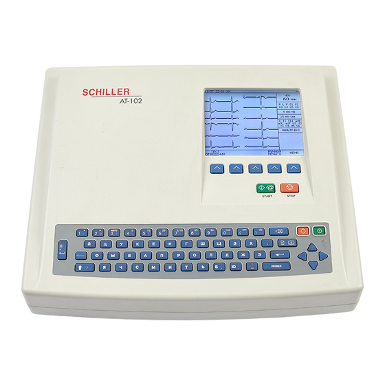
Page 22: Main Components Of The
AT-102 Service Handbook Introduction Main Components of the AT-102 Keypad and dedicated function keys Patient cable connector RS-232 for any of the following: ° connection of an ergo device ° connection of a spiro sensor ° connection of a modem or a PC for export of stored recordings Softkey control LCD Display. -
Page 23: Back Panel
Mains connector (with fuse below) CAUTION: All externally connected hardware must be approved by SCHILLER. Connection of any hardware not approved by SCHILLER is at the owner`s risk. The unit guarantee may also be invalid. Article Number 2. 540 028... -
Page 24: Power Supply
(nom. 230V) working. The setting is indicated by the indented metal strip on the fuse panel. Contact your dealer if the voltage needs to be changed. Switching On and Off The AT-102 is switched on with the green ON key and off with the red OFF key. These keys are situated on the top right of the keypad. -
Page 25: Changing A Mains Fuse
Potential Equalisation The potential equalisation stud at the rear of the unit can be used to equalise the ground potential of the AT-102 to that of all mains powered equipment in the vicinity. Use the hospital or building common ground. -
Page 26: Keypad
AT-102 Service Handbook Introduction Keypad... - Page 27 Section 1 AT-102 ECG Service Handbook Operating Elements Introduction Softkeys - the function of these keys changes depending on the screen displayed. The function of these keys is shown on the screen above the keys. If nothing is written above a softkey, it has no function for the current screen.
-
Page 28: Lcd Screen
AT-102 Service Handbook Introduction LCD Screen The display will vary according to the current task being carried out. In all screens however, the top and bottom lines always display the same information: the top line displays system information (time, patient, power source etc.,), and the bottom line always gives the softkey options. -
Page 29: Ecg Recorder Service Handbook
Section 1 AT-102 ECG Service Handbook Operating Elements Introduction Items 4 to 10 are specific for ECG acquisition only: Current Heart Rate (averaged over 4 beats and refreshed every 2 seconds). The HR is also given on a manual printout. Note that with an auto mode printout the HR is averaged over the full 10 seconds of the recording. -
Page 30: Ecg Settings
AT-102 Service Handbook ECG Settings The AT-102 ECG and system settings are entered by selecting 'setup' from the initial screen: The following pages detail the programmable ECG parameters. NOTE: In units where the interpretation option is not installed, interpretation state- ments, cannot be displayed. -
Page 31: Auto Format 1 And 2
Use the Up/Down softkeys to highlight the various options. Auto Format 1 and 2 Two separate Auto formats can be defined for the AT-102. Use the NEXT softkey to confirm setting and to move onto the next screen (Format 2). -
Page 32: Average Cycles
A vertical marker shows the beginning and end of P wave and QRS, and the end of the T wave Interpretation Select yes or no to print interpretation statement Full details of the interpretation option are given in the SCHILLER ECG Measurement and Interpretation booklet (art. No. 2.510 179). 1.14... -
Page 33: Filters
Section 1 AT-102 ECG Service Handbook Operating Elements ECG Settings Filters There are five different filters which can be set individually as follows: Baseline filter The cutoff frequency of the filter is set on the top line. The cutoff can be 0.05Hz, 0.15Hz or 0.3Hz. -
Page 34: Myogram Filter
(on), or not applied to a recording (off). Smoothing Filter (SCHILLER SSF) The smoothing filter (SSF: SCHILLER smoothing filter) is a low pass filter to suppress high frequency artefacts between the QRS complexes. When this filter is switched on, `SSF` is shown on the bottom line of the automatic printout. -
Page 35: Interpretation
Section 1 AT-102 ECG Service Handbook Operating Elements ECG Settings Interpretation The interpretation settings enable the user to determine whether or not certain comments will be added to the interpretation statements on the ECG printout. Furthermore, the patient’s age can be assumed (<30 or >30). Low or high can also be set for interpretation sensitivity. -
Page 36: Leads
AT-102 Service Handbook ECG Settings Leads Defining Lead Sequence & Printout The required settings can be selected as follows: Lead Sequence Select between: Standard lead sequence or Cabrera lead sequence Signals Select between: Simultaneous - all ECG leads are printed in the same time segment... - Page 37 Section 1 AT-102 ECG Service Handbook Operating Elements ECG Settings The lead group settings allow extra leads to be displayed on the screen when set to `on`. The following lead groups can be displayed: Rhythm Lead Group II, avF, III...
-
Page 38: Stress Settings
AT-102 Service Handbook Stress Settings The AT-102 Stress ECG settings are entered by selecting 'Setup' and 'Stress Settings' from the initial screen: The following pages detail the stress settings for the AT-102. 1.20... -
Page 39: General Settings
AT-102 ECG Service Handbook Operating Elements Stress Settings General Settings Selecting the ERGO Device Ergo devices available for use with the AT-102 are as follows: Bikes: The Ergoline digitally controlled exercise bicycle 900 / 911 SECA CT100 mod.545 Treadmills: The Ergoline digitally controlled treadmill TM435/TM4000ES... -
Page 40: Selecting The Default Test Protocol
AT-102 Service Handbook Stress Settings Selecting the Default Test Protocol Two protocols for a bike and two for a treadmill are available for selection when starting a stress test - the two protocols displayed when starting a stress test are defined here. -
Page 41: Defining / Editing Exercise Protocols
Section 1 AT-102 ECG Service Handbook Operating Elements Stress Settings Defining / Editing Exercise Protocols For a bicycle the following can be defined: Protocol Name - The name defined here appears in the general stress settings (when selecting the two default bike protocol (see previous page) -
Page 42: Factory Programmed Treadmill Protocols
AT-102 Service Handbook Stress Settings Factory programmed Treadmill Protocols One factory programmed Treadmill protocols is availbale as follows: Bruce Stage Duration Speed Elevation 3 min 2.7km/h (1.7mph) 3 min 4.0km/h (2.5mph) 3 min 5.4km/h (3.4mph) 3 min 6.7km/h (4.2mph) 3 min 8.0km/h (5.0mph) -
Page 43: System Settings
Section 1 AT-102 ECG Service Handbook Operating Elements System Settings The AT-102 system settings are entered by selecting 'setup' and 'system settings' from the initial screen: The following pages detail system settings for the AT-102. 1.25 Article Number 2. 540 028... -
Page 44: Unit
AT-102 Service Handbook System Settings Unit User Identification (User ID) The user identification is printed on all recordings. The user ID can be the department, doctor or hospital etc. Select User ID and a blinking cursor is present - enter up to 30 characters via the keypad. -
Page 45: Language
Section 1 AT-102 ECG Service Handbook Operating Elements System Settings Language Several languages are already programmed into the unit. Select the language for the screen display and for the printout. The language will also set the units used by the system. -
Page 46: Communication
AT-102 Service Handbook System Settings Communication Baudrate Select a Baud rate between 115200 and 9600 Baud, according to the modem/computer used. Most computers can connect at 115200 Baud and the standard modem speed is 57600 Baud. If problems are experienced during transmission reduce the Baud rate. -
Page 47: Test And Information
Section 1 AT-102 ECG Service Handbook Operating Elements System Settings Test and Information A code of the options installed is given after the software version. These are as follows: Interpretation Stress Memory (Standard) 1.29 Article Number 2. 540 028 SCHILLER AG 2002... -
Page 48: Obtaining A Printout Of All Current Settings
AT-102 Service Handbook System Settings Obtaining a printout of all current settings To obtain a printout press the `PRINT SETUP` softkey A printout of the defined settings will be produced and gives the following information, depending on the installed software:... - Page 49 Section 1 AT-102 ECG Service Handbook Operating Elements System Settings Filter Baseline Filter 0.05, 0.15 or 0.30 Hz Mains Filter 50, 60 Hz or OFF (-) Myogram Filter 25 or 35 Hz, ON (+) or OFF (-) SSB Filter Smoothing Filter Enabled (+) or Suppressed...
-
Page 50: Communications Test
When this is selected, test options are given for the RS-232 communication port. Use this test if the RS-232 port is suspected of malfunction. A special test plug is used to carry out the UART test. Full details if checking the RS-232 port is given in the AT-102 Service Handbook. -
Page 51: Default Settings
Section 1 AT-102 ECG Service Handbook Operating Elements System Settings Default Settings To reset the unit to the base default settings, press the `BASE INIT` softkey. As the unit resets to the default values a message is briefly displayed on the LCD. The base settings (Defaults) are given on the following page. -
Page 52: Unit Defaults Table
AT-102 Service Handbook System Settings Unit Defaults Table Settings Standard With Interpretation Language As set As set Auto Format 1 ECG: 25mm/s, short (o) ECG : 25mm/s, short (o) Rhythm Leads V1 Rhythm Leads V1, II MECG: 2*6 (50mm/s + 1) - Page 53 Section 1 AT-102 ECG Service Handbook Operating Elements System Settings Settings Standard With Interpretation Spiro FVC=f(t) on(+) FVC=f(t) on(1) F=f(v) on(+) F=f(v) on(+) Diagn.on(+) Diagn.on(+) PEF (l/min)on(+) PEF (l/min)on(+) Axis 10 mm/s Axis 10 mm/s Stress Bike 900 / 911...
- Page 54 AT-102 Service Handbook 1.36...
-
Page 55: Section 2 Functional Overview
Section 2 AT-102 Service Handbook Functional Overview Section 2 Functional Overview Article Number 2. 540 028 SCHILLER AG 2002... -
Page 56: Introduction
AT-102 Service Handbook Introduction This chapter provides a functional overview of the AT-102 electronics. The aim of this overview is to enable the service engineer to identify processing paths in order to help identify possible faulty modules. A functional block diagram supports the text. - Page 57 Section 2 AT-102 Service Handbook Functional Overview Article Number 2. 540 028 SCHILLER AG 2002...
-
Page 58: Mk 18 - 1 Main Board
AT-102 Service Handbook MK 18 - 1 Main Board Power Supply The mains supply is full wave rectified to produce an unregulated dc supply of approximately 30 V (+U). This voltage is used by a switched voltage generator to produce +UD (13.5V). -
Page 59: Printer Timing
Section 2 AT-102 Service Handbook Functional Overview MK 18 - 1 Main Board Printer Timing Strobe generation is controlled by the CPU when one complete pixel line of data is ready to be written. Pulse length of STRB1 and STRB2 (each of which controls half of the pixel array) depends from TPH temperature and so form the pulse width of the TPHT signal. -
Page 60: Ecg Signal
/ serial and serial / parallel conversion for the transmission and reception of data and provide signal level compatibility with RS-232 standard. External Modem An external modem can be connected to the RS-232 output from the AT-102 and be used for transmitting memory contents over a telephone line. -
Page 61: Top Assembly
Section 2 AT-102 Service Handbook Functional Overview Top Assembly LCD Screen The LCD power supply produces the high voltage for the LCD backlight and the contrast voltage. LCD data is stored in a video RAM and the LCD controller converts the data to the proper form for the LCD screen. - Page 62 AT-102 Service Handbook...
-
Page 63: Section 3 Fault Finding
Section 3 AT-102 Service Handbook Fault Finding Section 3 Fault Finding Article Number 2. 540 028 SCHILLER AG 2002... -
Page 64: Introduction
AT-102 Service Handbook Introduction The AT-102 is designed to be simple to use and simple to service: the service philosophy of the AT-102 is module and board replacement (no details are given in this book for board repair). The purpose of this chapter is to provide fault-finding procedures that will quickly and efficiently identify a fault to a specific module. -
Page 65: Fault Finding Chart
(SHEET C - GENERAL PRO- BLEMS) SHEET NOTE: The removal and replacement instructions and the location of all boards, cable assemblies and connectors are given in Chapter 4. AT-102 Initial Fault Diagnosis Chart (Sheet 1) Article Number 2. 540 028 SCHILLER AG 2002... -
Page 66: Initial Fault Diagnosis Chart (Sheet 2)
1. THE PAPER TRAY MOTOR CONNECTOR AND SWITCH 2. THE INTERFACE BOARD CHECK ALL PARAMETER SETTINGS. CHECK THE TEST SCREEN AND ENSURE THAT PARAME- TERS ARE IN TOLERANCE. CONTACT SCHILLER IF FAULT CANNOT BE FOUND AT-102 Initial Fault Diagnosis Chart (Sheet 2) -
Page 67: Fault Diagnosis Chart (Sheet A - Power Problems)
REPLACE THE MAINS ASSEMBLY SHORT CIRCUIT IN THE SHORT CIRCUIT IN THE MAINS TRANSFORMER. POWER SUPPLY. REPLACE REPLACE THE MAINS THE MAIN BOARD TRANSFORMER AT-102 Fault Diagnosis Chart (Sheet A - Power Problems) Article Number 2. 540 028 SCHILLER AG 2002... -
Page 68: Fault Diagnosis Chart (Sheet B - Power Problems)
ARE ALL POWER MAIN BOARD SUPPLIES OK? 1. REPLACE THE CABLE ASSEMBLY BETWEEN THE MAIN BOARD AND THE LCD (BASE ASSEMBLY TO TOP ASSEMBLY). 2. REPLACE THE MAIN BOARD 3. REPLACE THE LCD. AT-102 Fault Diagnosis Chart (Sheet B - Power Problems) -
Page 69: Fault Diagnosis Chart (Sheet C - General Problems)
CHECK THE CABLE ASSEMBLY BETWEEN THE POWER SUPPLYAND THE LCD (BOTTOM ASSEMBLY TO TOP ASSEMBLY). REPLACE REPLACE THE LCD. REPLACE THE VIDEO/LCD CONVERTER (MAIN BOARD) AT-102 Fault Diagnosis Chart (Sheet C - General Problems) Article Number 2. 540 028 SCHILLER AG 2002... -
Page 70: Fault Diagnosis Chart (Sheet D - Printer Problems)
POSITION ? NECESSARY CHECK AND ADJUST THE PAPER MARK DETECTOR AND CURRENT LIMITER THRESHOLDS AS DETAILED IN CHAPTER 5. DOES THE PROBLEM STILL EXIST? REPLACE: 1. MAIN BOARD 2. THERMAL PRINTER AT-102 Fault Diagnosis Chart (Sheet D - Printer Problems) -
Page 71: Fault Diagnosis Chart (Sheet F - Exercise Mode Problems)
ERGOMETERS CAN BE TEST EQUIPMENT USED WITH THE AT-102 USED? CHECK RS INTERFACE SETTING DETAILED IN CHAPTER 5 REPLACE: THE MAIN BOARD AT-102 Fault Diagnosis Chart (Sheet F - Exercise Mode Problems) Article Number 2. 540 028 SCHILLER AG 2002... -
Page 72: Fault Diagnosis Chart (Sheet G - Spirometry Problems)
CORRECT AND THAT ALL SETTINGS ARE CORRECT. SEE AT-102 USER GUIDE CHANGE CAN THE 1. MOUTHPICE CALIBRATION 2. FLOW SENSOR. PROCEDURE BE 3. MAIN BOARD CARRIED OUT? POSSIBLE OPERATOR ERROR. AT-102 Fault Diagnosis Chart (Sheet G - Spirometry Problems) 3.10... -
Page 73: Fault Diagnosis Chart (Sheet H - Communication (Rs) Problems)
1. CHECK THE +12V AND -12V SUPPLY VOLTAGES SETTING CORRECT? 2. CHANGE THE MAIN BOARD POSSIBLE OPERATOR ERROR. CHECK ALL CABLE ASSEMBLIES. REPLACE IF NECESSARY AT-102 Fault Diagnosis Chart (Sheet H - Communication (RS) Problems) 3.11 Article Number 2. 540 028 SCHILLER AG 2002... -
Page 74: Functional Check
AT-102 Service Handbook Functional Check Corrective action if result not Test Procedure Result Connect unit to mains supply. Mains indicator (LED) is lit. Check mains fuse on the back panel and replace if necessary. If problem remains, replace main board... -
Page 75: Thermal Printer Check
Section 3 AT-102 Service Handbook Fault Finding Thermal Printer Check To check the printer and to ensure that every pixel is operational, a built-in printer test is provided. Carry out the printer check from the ECG acquisition screen by pressing the FN key followed by the MANUAL PRINT softkey: A `wavy line` test printout is given. -
Page 76: Print Head Alignment And Print Head Tension
AT-102 Service Handbook Thermal Printer Check Print Head Alignment and Print Head Tension The print head tension (the pressure that the print head exerts on the printer paper) is achieved with two springs exerting pressure on the print head: the print head tension cannot be adjusted. -
Page 77: Interface (And Spiro Check)
Section 3 AT-102 Service Handbook Fault Finding RS-232 Interface (and Spiro Check) There are no specific tests that can be performed on the RS-232 interface. However the RS- 232 (UART) settings can be checked to ensure correct protocol and speed. If a spiro sensor is connected to the RS-232 connector, the sensor type can be displayed to ensure that it is the correct type. - Page 78 AT-102 Service Handbook 3.16...
-
Page 79: Section 4 Module Removal And Replacement
Section 4 AT-102 Service Handbook Module Removal and Replacement Section 4 Module Removal and Replacement Article Number 2. 540 028 SCHILLER AG 2002... - Page 80 AT-102 Service Handbook Remove top assembly In Base assembly access to : Paper tray Main Board MK Battery pack assembly and 18-1 connectors motor ECG and battery Mains transformer Thermal printer charge voltage and connector potentiometers Remove top assembly In Top assembly...
-
Page 81: Introduction
Section 4 AT-102 Service Handbook Module Removal and Replacement Introduction This Chapter provides an overview of the procedures to remove and replace the modules that are spared at service level. The instructions given in this chapter are autonomous, with each module containing the following: •... -
Page 82: Safety Notices
When carrying out these procedures beware that potentially lethal voltages are present. CAUTIONS The AT-102 contains static sensitive CMOS components; observe antistatic precau- tions: When carrying out any maintenance procedures always place the unit on an earthed antistatic mat. -
Page 83: Physical Overview
Module Removal and Replacement Physical Overview The AT-102 unit is enclosed in a two part, medical standard, moulded plastic case. The top part contains the keyboard and the LCD screen with the base section containing all the electronics of the unit, the RS-232 interface, the thermal printer, the paper tray, the battery and mains transformer. -
Page 84: Exploded View Lower Casing
AT-102 Service Handbook Exploded View Lower Casing EMC shield (ECG Processing Part) IMPORTANT Mains Isolation Shield. This must placed between Main Board MK 18-1 the mains transformer and board DC Motor with Cable (for EMC shield Mains paper tray) Transformer... -
Page 85: Exploded View Upper Casing
Section 4 AT-102 Service Handbook Module Removal and Replacement Exploded View Upper Casing Recess for LCD Keyboard Foil Article Number 2. 540 028 SCHILLER AG 2002... -
Page 86: Prerequisites, Test Equipment, Tools, And Accessories
The following list gives the tools, test equipment and accessories required to carry out all removal and replacement procedures, functional tests, calibration procedures and adjustments that can be carried out on the AT-102. The test equipment given here is general. If specific recommendation for test equipment is required, please contact the SCHILLER service department. -
Page 87: Opening And Closing The Case
Section 4 AT-102 Service Handbook Module Removal and Replacement Opening and Closing the Case Top Assembly Removal The Top Assembly is secured to the base assembly with seven recessed screws. Access to the screws is gained from the underside of the unit. To remove the Top Assembly,... - Page 88 AT-102 Service Handbook Opening and Closing the Case Support the top casing in an `upright` position to prevent straining the cable assemblies and connectors. 4.10...
-
Page 89: Top Assembly Replacement
Section 4 AT-102 Service Handbook Module Removal and Replacement Opening and Closing the Case Top Assembly Replacement To replace the Top Assembly proceed as follows: Check that all boards and components are firmly secured. Check for loose screws. Ensure that no screws or foreign bodies are loose in the bottom of the case. -
Page 90: Main Board Mk 18
Ensure that the mains cable is removed before commencing CAUTION: The main board contains static sensitive components; observe antistatic precautions. Open the AT-102 casing as described previously, support the top assembly. From the rear of the unit, unscrew the support securing screws. 4.12... - Page 91 Section 4 AT-102 Service Handbook Module Removal and Replacement Main Board MK 18 - 1 Carefully hinge the top assembly so that the top assemblies are apart as shown Disconnect all connectors on the board including the live and the neutral bayonet connectors to the mains connector.
-
Page 92: Board Replacement
AT-102 Service Handbook Main Board MK 18 - 1 Board Replacement To replace the Main board MK 18-1 proceed as follows: Position the board and secure at the 12 fixing points Reconnect all connecters P9 (under) P15 (under) Ext Printer... -
Page 93: Printer Tray And Thermal Printer
Section 4 AT-102 Service Handbook Module Removal and Replacement Printer Tray and Thermal printer CAUTION: The thermal printer contents is static sensitive; observe antistatic precau- tions. The printer is tensioned with two springs under the retaining bar. Take great care when removing the four screws not to lose the springs. -
Page 94: Battery Pack
AT-102 Service Handbook Battery Pack Battery Pack Removal WARNING: The Warnings and Cautions at the beginning of the chapter must be observed. Ensure that the mains cable is removed before commencing To remove the Battery Pack proceed as follows: Remove the top assembly as detailed previously. -
Page 95: Keyboard
Section 4 AT-102 Service Handbook Module Removal and Replacement Keyboard The keyboard comes as a complete assembly with the top casing. The part number of the keyboard is given in Chapter 6. 4.17 Article Number 2. 540 028 SCHILLER AG 2002... -
Page 96: Lcd Screen Board
AT-102 Service Handbook LCD screen board WARNING: The Warnings and Cautions at the beginning of the chapter must be observed. Ensure that the mains cable is removed before commencing CAUTION: The main board contains static sensitive components; observe antistatic precautions. -
Page 97: Section 5 Adjustments, System Upgrades And Software Updates
Section 5 AT-102 ECG Service Handbook Adjustments Section 5 Adjustments, System Upgrades and Software Updates Article Number 2. 540 028 SCHILLER AG 2002... - Page 98 AT-102 Service Handbook...
-
Page 99: Introduction
Specific warnings and cautions are given in the text where applicable. The part numbers for all replaceable modules are given in Chapter 6. The AT-102 has the following adjustments: • Battery Charge Voltage (VR3 on the main board MK 18-1) •... -
Page 100: Safety Notices And Conditions
Never strain the cable assemblies. The procedural steps given for each module must be followed in the order given. The outer surfaces of the AT-102 are susceptible to abrasion damage. To prevent scratching, always place on a soft, non-abrasive cloth. Conditions The unit must be placed on an antistatic mat and antistatic precautions observed when any maintenance is carried out on the AT-102. -
Page 101: Test Equipment
The following proprietary and dedicated test equipment is required to fault find and carry out all board checks and adjustments on the AT-102. The list of proprietary equipment is not comprehensive. Recommendations of suitable proprietary test equipment can be obtained from the SCHILLER Service Department. Proprietary Test Equipment/Tools •... -
Page 102: Main Board Mk 14-10 Adjustment Locations
AT-102 Service Handbook Main Board MK 14-10 Adjustment Locations Component Location MK18-1 (Component Side) Video (VGA) Ext Printer P2 (under) internal battery (Comm Module) RS-232 Patient... -
Page 103: Battery Charge Voltage
Battery Charge Voltage Precautions and Requirements The unit must be placed on an antistatic mat and antistatic precautions observed when any maintenance is carried out on the AT-102. The room temperature should be between 18 and 28 degrees. Tools and Equipment •... -
Page 104: Paper Mark Detector Check
AT-102 Service Handbook Paper Mark Detector Check This procedure is a check only. There are no presets that can be adjusted. If this check fails the main board MK 18-1 must be replaced. Tools, Equipment and Material Digital voltmeter Small flat bladed screwdriver... - Page 105 Section 5 AT-102 ECG Service Handbook Adjustments Paper Mark Detector Check Disassemble the unit as detailed in Chapter 4. Clean the photocell (situated on the opposite side to the dc motor) with a 70% alcohol solution. Allow to completely dry.
-
Page 106: Ecg Amplifier +2V, -2V And Pwm Ramp Time Adjustment
AT-102 Service Handbook ECG Amplifier +2V, -2V and PWM Ramp Time Adjustment The ±2V voltage rails generated on the ECG Amplifier board are used as a reference by the measurement and PWM circuits. NOTE The ±2V reference voltages, and the PWM ramp must both be adjusted at the same time. - Page 107 Section 5 AT-102 ECG Service Handbook Adjustments ECG Amplifier Reference voltage Switch the unit on and measure the voltage difference between the +2V reference and the -2V reference on pins 1 and 7 of operational amplifier U79. Adjust trimmer VR1 to achieve a voltage difference of 4000 mV ±2mV.
-
Page 108: Service Screen
AT-102 Service Handbook Service Screen The service screen provides information of the patient cable and electrodes and gives the value of certain reference voltages and important internal offset values. These values are for information only. The service screen also gives variable settings and measurements that can be set by the service engineer;... - Page 109 Section 5 AT-102 ECG Service Handbook Adjustments Service Screen (cont.) ECG Reference Voltage This provides measurements and setting facilities for the reference voltage used for accurate measurement of ECG signals Uref+ This gives the value of the reference voltage used in the multiplexer circuit on the ECG Amplifier.
-
Page 110: Upgrading The Unit / Updating The Software
Installing New Software Options (Upgrade) Use the upgrade option to install any available software options (e.g. Exercise). To install new options in the AT-102, a code must be entered. This code must be obtained from SCHILLER. To install software option proceed as follows: Enter the TEST and INFO screen: SETUP >... - Page 111 Section 5 AT-102 ECG Service Handbook Adjustments Upgrading the Unit / Updating the Software Select UPGRADE. The following is displayed: Enter the upgrade code When the correct code is entered, acceptance of the code is indicated by a series of beeps.
-
Page 112: Updating The System Software
Updating the System Software The AT-102 software is updated using a PC program called SWUP. To update the software, the RS-232 connector on the side of the AT-102 is connected to a PC using a RS-232 to RS-232 cable assembly. - Page 113 Upgrading the Unit / Updating the Software Install the SWUP program on the PC (available from the SCHILLER Mailbox). Follow the instructions given by the program. Open the SWUP program through the SWUP icon on the desktop or via the Startup - Schiller-Menu.
- Page 114 AT-102 Service Handbook 5.18...
-
Page 115: Section 6 Spare Parts
Section 6 AT-102 Service Handbook Spared Parts Section 6 Spare Parts Article Number 2. 540 028 SCHILLER AG 2002... -
Page 116: Ordering Information
AT-102 Service Handbook Ordering Information WARNING Always use SCHILLER replacement parts and disposables, or products approved by SCHILLER. Failure to do so may endanger life and invali- date the guarantee. NOTE Your local representative stocks all the disposables and accessories avail- able for the AT-102. -
Page 117: Spare Parts
Section 6 AT-102 Service Handbook Spared Parts Spare Parts The parts listing for the AT-102 at the time of print was being revised. Please contact your local agent for parts listing. Article Number 2. 540 028 SCHILLER AG 2002... - Page 118 AT-102 Service Handbook...
-
Page 119: Section 7 Technical Data
Section 7 AT-102 Service Handbook Technical Data Section 7 Technical Data The technical data is subject to change. Article Number 2. 540 028 SCHILLER AG 2002... - Page 120 AT-102 Service Handbook...
-
Page 121: Technical Data
Section 7 AT-102 Service Handbook Technical Data Technical Data System: Dimensions: 400 x 330 x 101 mm, approx. 5 kg Built-in monitor: 120 x 90 mm effective display area, 320 x 240 dots resolution On-screen status indicators: Battery status Date, time... -
Page 122: Safety Standards
AT-102 Service Handbook Technical Data Safety Standards: Safety standard: CF according IEC 60601-1 and IEC 601-2-25 Protection class: I according to IEC 60601-1 (with internal battery), IIa according to EEC directive 93/42 (medical protection class) Conformity: CE according to 93/42/EEC... -
Page 123: Technical Data For Spirometry (Option)
Section 7 AT-102 Service Handbook Technical Data Technical Data Recording track: 6/12-channel presentation, optimal positioning on a width of 200 mm, automatic baseline adjustment Filter: Myogram filter (muscle tremor filter): 25 Hz or 35 Hz, can be switched on/off ECG amplifier:... - Page 124 AT-102 Service Handbook Technical Data SPIROVIT SP-250 Pneumotach Flow sensor for pulmonary function testing with disposable mouthpiece: Dimensions of SP-250: 118 x 36 x 28 mm, approx. 120 g; 4.6 x 1.4 x 1.1 in., approx. 0.26 Ibs Measuring method: Pneumotachometer Measuring accuracy: According ATS <...
-
Page 125: Standard
Section 7 AT-102 Service Handbook Technical Data Technical Data Standard CARDIOVIT AT-102 ECG with 12 simultaneous leads, pacemaker detection, automatic ECG measurement. Accessories: 1 10-lead patient cable 1 set of electrodes or disposable electrodes 1 power cable 1 pack chart paper... - Page 126 AT-102 Service Handbook...
-
Page 127: Annex A Glossary
Annex A AT-102 Service Handbook Glossary Annex A Glossary Annex Article Number 2. 540 028 SCHILLER AG 2002... -
Page 128: Introduction
The following list provides a glossary of the important signals and acronyms used in the circuit diagrams for the SCHILLER instruments. They will not all apply to the AT-102 Only abbreviations that are specific to SCHILLER equipment are included here. General electrical and electronic abbreviations are not included. -
Page 129: Acronyms
Annex A AT-102 Service Handbook Glossary Acronyms ..OS Offset signal (on the ECG amplifier). A(1...n) CPU Address Bus ALBEEP(or BEEP) Alarm beeper signal to the audio amplifier. The frequency of this signal is about 1000 Hz. ANA1, ANA2 Analog input from the experimental inputs DC1 and DC2... - Page 130 AT-102 Service Handbook DS.. Data strobe. DSP.. Digital signal processor (on program pack). DTACK Transfer data acknowledge. Bus signal to acknowledge transfer of data. Outgoing serial data, turns modem ON. ECGI ECG in - serial ECG data to the CPU sent over the optical interface.
- Page 131 Annex A AT-102 Service Handbook Glossary LEDMAINS Signal indicating mains connected to operate LED indicator on the keyboard. Liquid crystal address - enable. LCD KONT LCD contrast - sets the -18 V voltage level (from which the LCD backlight power is generated) and thus the contrast of the screen.
- Page 132 Upper column address strobe (for dynamic RAM). UD1, UD2 Upper data strobe - used for generating UOE and UWE. Upper data strobe - used on the Schiller gate array. UOE, USRAM Upper output enable - for static RAM. Voltage rectified from the mains input and regulated to approximately +15 V.
- Page 133 Annex A AT-102 Service Handbook Glossary Upper write enable. Unregulated dc supply from mains (approximately 30V). +UBU Back-up voltage for the real time clock and static RAM. Unswitched regulated dc voltage used as power source for the switched supply +US. The voltage is 13.5 V when mains is connected, or battery voltage when mains is not connected.
- Page 134 AT-102 Service Handbook Annex...
-
Page 135: Engineering Drawings
Annex B AT-102 User Guide Circuit Diagrams and Engineering Drawings Annex B AT-102 Circuit Diagrams and Engineering Drawings Annex Article Number 2. 540 028 SCHILLER AG 2002... -
Page 136: Index
AT-102 Service Handbook Index Index Index.1 Article Number 2. 540 028 SCHILLER AG 2002... - Page 137 AT-102 Service Handbook Index Symbols +2V, -2V and PWM Ramp Time Adjustment Date and Time 1.26 5.10 Default Settings 1.33 Default Test Protocol 1.22 Defining / Editing Exercise Protocols 1.23 Disposal Instructions xi Article Number ii Associated Documents ii Auto-Centering 1.18 Average Cycles 1.14...
- Page 138 Printer Timing 2.5 Printout of all current settings 1.30 Program Memory 2.4 Proprietary Test Equipment/tools 5.5 PWM Ramp Time Adjustment 5.10 Main Components of the AT-102 1.4 Mains filter 1.16 Markings 1.14 Measurements, Markings and Interpretation 1.14 MK 14-10 Adjustment Locations 5.6 Recycling xi Mode 1.28...
- Page 139 AT-102 Service Handbook Safety Notices xii, xiii, xiv Udif 5.13 Safety Standards 7.4 Unit Defaults 1.34 SCHILLER SSF 1.16 Uoff 5.13 Selecting the ERGO Device 1.21 Upgrade 1.32, 5.14 Sequential 1.18 Upgrading the System Options and Updating software Service Printout 5.12, 5.13 5.14, 5.15...
- Page 140 AT-102 Service Handbook Index Index.5 Article Number 2. 540 028 SCHILLER AG 2002...
Need help?
Do you have a question about the AT-102 and is the answer not in the manual?
Questions and answers
Добрый день! Поверка кардиографа обязательна? Если да, какая периодичность?
Calibration is not mandatory for the Schiller AT-102 electrocardiograph, as it is described as calibration and maintenance free.
This answer is automatically generated