Table of Contents
Advertisement
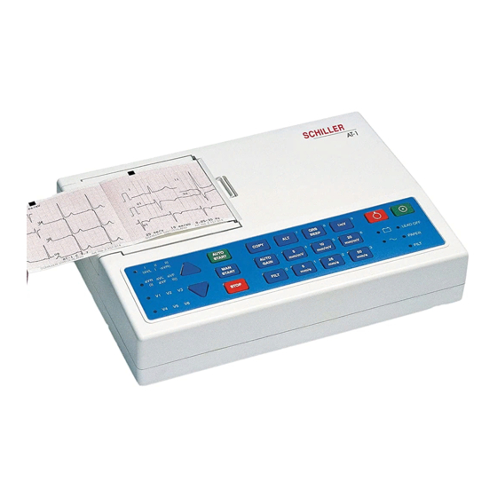
SCHILLER AT-1 / AT-1smartprint ECG Unit
SERVICE HANDBOOK Issue b June 2001
AT-1 /
AT-1smartprint
ECG unit
Service Handbook
SCHILLER AG
Altgasse 68
CH-6341 Baar, Switzerland
Phone: + 41 41 766 42 42
Fax: + 41 41 761 08 80
Home page: http://www.schiller.ch/
June
2001
Article Number: 2.540022
1
Art.No. 2.540022
Advertisement
Table of Contents

Related Manuals for Schiller CARDIOVIT AT-1


Summary of Contents for Schiller CARDIOVIT AT-1
- Page 1 SCHILLER AT-1 / AT-1smartprint ECG Unit SERVICE HANDBOOK Issue b June 2001 AT-1 / AT-1smartprint ECG unit Service Handbook SCHILLER AG Altgasse 68 CH-6341 Baar, Switzerland Phone: + 41 41 766 42 42 Fax: + 41 41 761 08 80 Home page: http://www.schiller.ch/...
- Page 2 June 2001 Associated Documents Guide to the SCHILLER Interpretation and Measurement Program E/ D/ F Article No. 2. 510179 SCHILLER AT-1 / AT-1 smartprint User Guide - EDF Article No. 2. 510171 e Windows™ is a trademark of Microsoft Corporation.
- Page 3 The SCHILLER sales and service centre network is worldwide. For the address of your local distributer, contact your nearest Schiller subsidiary. In case of difficulty a complete list of all distributers and subsidiaries is provided on our internet site or can be supplied from our head office.
- Page 4 Warranty Terms of Warranty The SCHILLER AT-1 / AT-1 smartprint is warranted against defects in material and manufacture for the duration of one year (as from date of purchase). Excluded from this guarantee is damage caused by an accident or as a result of improper handling.
- Page 5 THE DEVICE MUST ONLY BE OPERATED USING BATTERY POWER IF THE EARTH CONNECTION IS SUSPECT OR IF THE MAINS LEAD IS DAMAGED OR SUSPECTED OF BEING DAMAGED. USE ONLY ACCESSORIES AND OTHER PARTS RECOMMENDED OR SUPPLIED BY SCHILLER AG. USE OF OTHER THAN RECOMMENDED OR SUPPLIED PARTS MAY RESULT IN INJURY INACCURATE INFORMATION AND / OR DAMAGE TO THE UNIT.
- Page 6 NOT USE E-BEAM OR GAMMA RADIATION STERILISATION. THIS UNIT IS CF CLASSIFIED ACCORDING TO IEC EN 60601-1. THIS MEANS THAT THE PATIENT CONNECTION IS FULLY ISOLATED AND DEFIBRILLATION PROTECTED. SCHILLER CAN ONLY GUARANTEE PROTECTION AGAINST DEFIBRILLATION VOLTAGE HOWEVER, WHEN THE ORIGINAL SCHILLER PATIENT CABLE IS USED.
- Page 7 SERVICE HANDBOOK Issue b June 2001 What is in this book THE SERVICE PHILOSOPHY FOR ALL SCHILLER UNITS IS FAULT FINDING TO MODULE LEVEL ONLY. THE PURPOSE OF THIS BOOK IS TO PROVIDE ALL THE INFORMATION NECESSARY TO ENABLE THE SERVICE ENGINEER TO EFFICIENTLY LOCATE AND REPLACE A FAULTY MODULE. THIS BOOK ASSUMES NO DETAILED KNOWLEDGE OF THE ECG UNIT BUT DOES REQUIRE THAT THE SERVICE ENGINEER IS FAMILIAR WITH STANDARD WORKSHOP PRACTICES.
- Page 8 What's in this book Chapter 7 - Technical Data The full technical specification of the AT-1 / AT-1 smartprint is given in this chapter. Index Circuit Diagrams & Board Layouts The circuit diagrams and component layouts are provided for all boards. These details are provided for information only.
- Page 9 SCHILLER AT-1 / AT-1smartprint ECG Unit SERVICE HANDBOOK Issue b June 2001 Contents Associated Documents Where to Obtain Service Warranty Safety Notices What is in this book CHAPTER 1 OPERATING ELEMENTS Introduction Location & Power The Keyboard AT-1/AT-1smartprint Short Form Operating Instructions...
- Page 10 Automatic Mode (ECG) Settings Interpretation Settings (C version only) Selecting Rhythm Leads Service Printout Installing Software Options Care & Maintenance Replacing the Recording Paper in the Internal Printer Thermal Paper Handling CHAPTER 2 FUNCTIONAL OVERVIEW Main Board MK 11-10 CHAPTER 3 FAULT DIAGNOSIS Fault Diagnosis Chart General Functional Check Procedures...
- Page 11 SCHILLER AT-1 / AT-1smartprint ECG Unit SERVICE HANDBOOK Issue b June 2001 Chapter 1 Operating Elements Art.No. 2.540022...
- Page 12 Introduction The AT-1 / AT-1 smartprint is a 3-channel ECG recorder with all (12) ECG signals simultaneously processed to provide instant ECG recordings. Three automatic recording modes - two for the internal printer and one for the external printer - can be individually preset to enable one button ECG recording of preferred print formats.
- Page 13 SCHILLER AT-1 / AT-1smartprint ECG Unit SERVICE HANDBOOK Issue b June 2001 Location & Power Location Do not keep or operate the device in a wet, moist, or dusty environment. Also avoid exposure to direct sunlight or heat from other sources. Do not allow the unit to come into contact with acidic vapours or liquids, as such contact may cause irreparable damage.
- Page 14 The Keyboard...
- Page 15 SCHILLER AT-1 / AT-1smartprint ECG Unit SERVICE HANDBOOK Issue b June 2001 AT-1/AT-1smartprint Short Form Operating Instructions Automatic ECG Recording with external printer connected and switched on: Prepare skin, hook up patient. Switch unit on, press ON Press AUTO to record and print externally...
- Page 16 Modes of Operation Automatic Mode a . without external printer connected or printer switched off Automatic Mode provides a printout giving 10 seconds of ECG recording of all 12 leads with a choice of 2 different formats (only for S version). The following can be programmed freely for each of the 2 formats before recording: •...
- Page 17 SCHILLER AT-1 / AT-1smartprint ECG Unit SERVICE HANDBOOK Issue b June 2001 Automatic Mode a . without external printer connected or printer switched off In automatic mode, a full 12-lead ECG is printed in one of two predefined formats with selectable sensitivity. These formats (see Settings) are selected by the user to suit his specific needs and requirements.
- Page 18 Automatic Mode b . with external printer With the external printer connected and switched on, only one Auto Mode format (selectable) is available. To start the automatic ECG recording in Automatic Mode, press the AUTO START key: For further information see paragraph `Automatic Mode (ECG) Settings` on page 30.
- Page 19 SCHILLER AT-1 / AT-1smartprint ECG Unit SERVICE HANDBOOK Issue b June 2001 Manual Mode Manual mode provides a real-time ECG printout of 3 selected leads with full control of parameter selection. This is only possible on the internal thermal printer.
- Page 20 Settings Each parameter is set by means of a code. This code comprises a combination of keys starting with the ALT key followed by two or three numbers. The setting is confirmed with the STOP key. As soon as the ALT key is pressed, the keyboard is dedicated to the programming function.
- Page 21 SCHILLER AT-1 / AT-1smartprint ECG Unit SERVICE HANDBOOK Issue b June 2001 Settings (cont.) The defined formats and settings for your unit can be checked as follows: ALT - 0 - 1 - any number A printout of the defined settings will be produced and gives the following information, depending on the installed software.
- Page 22 Settings (cont.) Default Settings To reset the unit to the basic default settings, proceed as follows: ALT - 0 - 6 - 6 C = WITH SETTINGS S = STANDARD M = MEASUREMENTS INTERPRETATION LANGUAGE AS SET AS SET AS SET LEADS STANDARD (S) STANDARD (S)
- Page 23 SCHILLER AT-1 / AT-1smartprint ECG Unit SERVICE HANDBOOK Issue b June 2001 Settings (cont.) Language The language is selected as follows: Language Selection AT-1 Language Selection AT-1 smartprint Entry Key Sequence Language Confirm Entry Key Sequence Language Confirm German German...
- Page 24 Settings (cont.) Filters There are three different filters which can be set individually as follows: • Baseline filter • Mains filter • Myogram filter Baseline Filter The digital Baseline filter suppresses excessive baseline drifts. The setting options are as follows: Baseline Filter Entry Key Sequence Filter Setting...
- Page 25 SCHILLER AT-1 / AT-1smartprint ECG Unit SERVICE HANDBOOK Issue b June 2001 Settings (cont.) Myogram Filter The Myogram filter suppresses disturbances caused by strong muscle tremor. The set value will be the new upper limit of the frequency range as soon as the FILTER key is pressed on or programmed as default when the unit is switched on.
- Page 26 Settings (cont.) Defining Lead Sequence & Printout The required settings can be selected as follows: Sequences, Print & Auto-centering Entry Key Sequence Definition Confirm Standard Lead Sequence Cabrera Lead Sequence Simultaneous Print Press STOP Sequential Print Auto-centering ON Auto-centering OFF Z-fold paper Confirm the selection by pressing the STOP key The selectable printout forms are:...
- Page 27 SCHILLER AT-1 / AT-1smartprint ECG Unit SERVICE HANDBOOK Issue b June 2001 Settings (cont.) Acoustic QRS Indication The acoustic QRS beep can be switched on or off at any time by pressing the QRS BEEP key. Time / Date (AT-1 smartprint only)
- Page 28 Automatic Mode (ECG) Settings, Internal Printer Two separate Auto formats can be defined for the internal printer in the AT-1 / AT-1smartprint. When defining auto format 1 the key sequence ALT - 1 precedes the setting. When defining auto format 2 the key sequence ALT - 2 precedes the setting.
- Page 29 Interpretation is omitted Press STOP 1 or 2 Interpretation is printed Confirm the selection by pressing the STOP key Full details of the interpretation option are given in the SCHILLER ECG Measurement and Interpretation booklet (art. No. 2.510 179). Art.No. 2.540022...
- Page 30 Automatic Mode (ECG) Settings, External Printer One Auto format can be defined for the external printer in the AT-1smartprint. When defining the auto format the key sequence ALT - 9 precedes the setting. The automatic mode format is detailed on the following pages. The ECG format is set as follows: ECG Format External printer Entry Key Sequence...
- Page 31 Printout Confirm Interpretation is omitted Press STOP Interpretation is printed Confirm the selection by pressing the STOP key Full details of the interpretation option are given in the SCHILLER ECG Measurement and Interpretation booklet (art. No. 2.510 179). Art.No. 2.540022...
- Page 32 Automatic Mode (ECG) Settings Interpretation Settings (C version only) The interpretation settings enable the user to determine whether or not certain comments will be added to the interpretation statements on the ECG printout. Furthermore, the patient’s age can be defined (<30 or >30) and if low or high sensitivity should be applied.
- Page 33 SCHILLER AT-1 / AT-1smartprint ECG Unit SERVICE HANDBOOK Issue b June 2001 Automatic Mode (ECG) Settings (cont.) Selecting Rhythm Leads The rhythm leads are printed out as defined. Two separate rhythm leads can be selected. The following formats can be set:...
- Page 34 Service Printout The service printout provides information about the patient cable and electrodes and gives the values of certain reference voltages and important internal offset values. These values are for information only. To obtain the service printout press ALT - 0 - 3 - 3 ECG Reference Voltage This provides measurements and setting facilities for the reference voltage used for accurate measurement of ECG signals...
- Page 35 To upgrade the AT-1 / AT-1 smartprint, for example from standard to M version, type the following: ALT - 0 - 4 - followed by the upgrade code (obtainable from SCHILLER). Acceptance of the code is indicated by a series of beeps. CAUTION MORE THAN 10 UNSUCCESSFUL ATTEMPTS TO ENTER THE CODE BLOCKS THE UNIT.
- Page 36 Care & Maintenance 12 Monthly Check The unit should undergo a technical safety check every 12 months. This safety check should include the following: • Visual inspection of the unit and cables. • Electrical safety tests according to IEC 601-1 Clause 19. •...
- Page 37 • Close the lid and press firmly until release catches. Press the STOP key to transport the paper to the start position. SCHILLER can only guarantee perfect printouts when SCHILLER original chart paper or chart paper of the same quality is used.
- Page 38 Thermal Paper Handling The thermal paper used in the AT-1 / AT-1smartprint requires slightly different handling to normal paper as it can react with chemicals and to heat. However, when the following points are remembered, the paper will give reliable results: The following points apply to both storage and when archiving the results.
- Page 39 SCHILLER AT-1 / AT-1smartprint ECG Unit SERVICE HANDBOOK Issue b June 2001 Chapter 2 Functional Overview Art.No. 2.540022...
- Page 41 SCHILLER AT-1 / AT-1smartprint ECG Unit SERVICE HANDBOOK Issue b June 2001 Introduction This chapter provides a functional overview of the AT-1 / AT-1smartprint electronics. The aim of this overview is to enable the service engineer to identify processing paths in order to help identify possible faulty modules.
- Page 42 Main Board MK 11-10 Power Supply The mains supply is full wave rectified to produce an unregulated dc supply of approximately 35 V (+U). This voltage is used by a switched voltage generator to produce +UD (13.5V). +UD charges the battery when mains is connected. When mains is not connected, +UD is the battery voltage.
- Page 43 SCHILLER AT-1 / AT-1smartprint ECG Unit SERVICE HANDBOOK Issue b June 2001 Main Board MK 11-10 (cont.) Paper Mark The pulsed paper mark signal from the printer is fed to a comparator. A detected paper mark supresses any (logic 0) pulses of PMARK at the output of comparator U38.
- Page 45 SCHILLER AT-1 / AT-1smartprint ECG Unit SERVICE HANDBOOK Issue b June 2001 Chapter 3 Fault Diagnosis Art.No. 2.540022...
- Page 46 Fault Diagnosis Chart...
- Page 47 SCHILLER AT-1 / AT-1smartprint ECG Unit SERVICE HANDBOOK Issue b June 2001 Introduction The AT-1 / AT-1smartprint is designed for easy use and service: the service philosophy of the AT-1 / AT-1smartprint is module replacement and not board repair. The purpose of this chapter is to provide fault-finding procedures that will quickly and efficiently identify a fault to a specific module.
- Page 48 General Functional Check Procedure The procedure detailed here is a general confidence check of the unit after an internal module or board has been replaced. It is not a full functional test (which can only be carried out with dedicated equipment in the factory) but is intended to provide a general confidence check in all the major AT-1 / AT-1smartprint functional areas.
- Page 49 SCHILLER AT-1 / AT-1smartprint ECG Unit SERVICE HANDBOOK Issue b June 2001 Internal Printer Check To check the printer and to ensure that every pixel is operational, a built-in printer test is provided. To carry out the printer check press: ALT - MAN START A test printout is given.
- Page 50 Printer Check External Printer Problems Possible Printer Problem Corrective Action External Inkjet printer No printout Check that the USB and the Centronics interface on the external printer are not simultaneously engaged. Poor quality printout. Make sure that the printer and the AT-1 smartprint are properly grounded via the potential equalisation stud.
- Page 51 SCHILLER AT-1 / AT-1smartprint ECG Unit SERVICE HANDBOOK Issue b June 2001 Chapter 4 Module Removal and Replacement Art.No. 2.540022...
- Page 52 Remove top assembly In Base Assembly access to : Mains trans- Paper tray Battery former and assembly interface pack connector and motor MK 11-2 Thermal Control and printer power supply board MK 11-10 Remove top assembly In Top Assembly access to : Keyboard...
- Page 53 SCHILLER AT-1 / AT-1smartprint ECG Unit SERVICE HANDBOOK Issue b June 2001 Introduction This chapter provides an overview of the procedures to remove and replace the modules that are spared at service level. The instructions given in this chapter are autonomous, with each module containing the following: •...
- Page 54 Warnings and Cautions WARNINGS BEFORE COMMENCING ANY REMOVAL OR REPLACEMENT PROCEDURES ENSURE THAT THE MAINS POWER SUPPLY IS SWITCHED OFF AND THAT THE MAINS CABLE IS REMOVED. CERTAIN CHECKS AND ADJUSTMENTS CAN ONLY BE CARRIED OUT WITH THE TOP ASSEMBLY REMOVED AND WITH MAINS CONNECTED.
- Page 55 AT-1 / AT-1smartprint. The test equipment given here is general. If specific recommendation for test equipment is required, please contact the SCHILLER service department. • Selection of posi-drive and flat-bladed screwdrivers •...
- Page 56 • Posi-drive screwdriver Test Equipment The following test equipment is required to carry out the functional test after unit assembly • SCHILLER Patient Cable • Patient Simulator e.g. phantom 320. Top Housing Removal The Top Housing is mounted on the Base Assembly and is secured to the Base Assembly with six screws;...
- Page 57 SCHILLER AT-1 / AT-1smartprint ECG Unit SERVICE HANDBOOK Issue b June 2001 Top Housing Replacement To replace the Top Housing proceed as follows: 1. Check that all boards and components are firmly secured. Check for loose screws. Ensure that no screws or foreign bodies are loose in the bottom of the case.
- Page 58 Physical Overview Keyboard connector Printer motor Patient connector View of the unit with the ECG interface board lifted upp.
- Page 59 To prove the integrity of the replaced board carry out the following functional check procedure: Switch on the unit and connect a SCHILLER patient cable to the ECG connector. Connect a suitable patient simulator to the ECG connector and press MAN START. Ensure that all the leads are printed.
- Page 60 Printer Tray Assembly and Thermal Printer Prerequisites • The Warnings and Cautions at the beginning of the Chapter must be observed. • The top housing must be removed as detailed previously. All external cable assemblies must be disconnected. Tools • Posi-drive screwdriver •...
- Page 61 SCHILLER AT-1 / AT-1smartprint ECG Unit SERVICE HANDBOOK Issue b June 2001 Thermal Printer Removal 1. Remove the top housing and the printer tray assembly as outlined above. 2. Turn the printer / paper tray assembly upside-down and unscrew the two printer retaining screws.
- Page 62 Control and Power Supply Board MK 11-10 The Control and Power Supply Board MK 11-10 is secured to the base assembly and located under the ECG Interface Board MK 11-2. Prerequisites • The Warnings and Cautions at the beginning of the chapter must be observed. •...
- Page 63 SCHILLER AT-1 / AT-1smartprint ECG Unit SERVICE HANDBOOK Issue b June 2001 Control and Power Supply board MK 11-10 Board Replacement To replace the Control and Power Supply Board MK 11-10 proceed as follows: 1. Position the board and secure at the 12 fixing points (four on the mains transformer) 2.
- Page 64 Battery Pack The battery pack is held in position with double-sided tape. Prerequisites • The Warnings and Cautions at the beginning of the Chapter must be observed. • The top housing must be removed and all external cable assemblies disconnected. Tools and Equipment Double-sided tape Parts...
- Page 65 SCHILLER AT-1 / AT-1smartprint ECG Unit SERVICE HANDBOOK Issue b June 2001 Battery Pack Settings After Battery Replacement (AT-1 smartprint only) Program all static settings which will have been lost when the battery was disconnected including date and time. Set Date ALT - 0 - 5 - 2 - D - D - M - M - Y - Y An acoustic signal confirms the changed setting.
- Page 66 Keyboard The keyboard comes as a complete assembly with the top housing. The part number for the keyboard complete with top housing is given in Chapter 6.
- Page 67 SCHILLER AT-1 / AT-1smartprint ECG Unit SERVICE HANDBOOK Issue b June 2001 Chapter 5 Adjustments Art.No. 2.540022...
- Page 68 Introduction This chapter provides the procedures necessary to check and adjust all service settings. Every procedure is self-contained and details the tools required to carry out adjustments, and the test equipment necessary. Any adjustments, special checks or functional tests that are required on the module, or on associated modules or software, are also detailed. In-text illustrations support the text where required and provide location details of connectors, test points and adjustment potentiometers.
- Page 69 SCHILLER AT-1 / AT-1smartprint ECG Unit SERVICE HANDBOOK Issue b June 2001 Warnings, Cautions and Conditions WARNING MAINS POWER IS POTENTIALLY LETHAL - DISCONNECT THE MAINS BEFORE DISASSEMBLING THE UNIT. ADDITIONALLY ENSURE THAT THE MAINS IS DISCONNECTED BEFORE CARRYING OUT ANY MAINTENANCE, CALIBRATION, CHECKS OR ADJUSTMENTS.
- Page 70 AT-1 / AT-1smartprint. The list of proprietary equipment is not comprehensive. Recommendations of suitable proprietary test equipment can be obtained from the SCHILLER Service Department. Proprietary Test Equipment/Tools • Digital Multimeter •...
- Page 71 SCHILLER AT-1 / AT-1smartprint ECG Unit SERVICE HANDBOOK Issue b June 2001 Battery Charge Voltage Precautions and Requirements The unit must be placed on an antistatic mat and antistatic precautions observed when any maintenance is carried out on the AT-1 / AT-1 smartprint. The room temperature should be between 18 and 28 °C.
- Page 72 ECG Amplifier Reference Voltage The +/- 2 V voltage rails generated on the ECG interface board are used as a reference by the measurement and the PWM (Pulse Width Modulation) circuits. NOTE: The ECG board reference voltage is given on the service printout and can be checked without disassembling the unit.
- Page 73 SCHILLER AT-1 / AT-1smartprint ECG Unit SERVICE HANDBOOK Issue b June 2001 ECG Amplifier Reference Voltage • Switch the unit on and measure the voltage difference between the +2 V reference and the -2 V reference on pins 1 and 7 of operational amplifier U100.
- Page 75 SCHILLER AT-1 / AT-1smartprint ECG Unit SERVICE HANDBOOK Issue b June 2001 Chapter 6 Spare Parts Art.No. 2.540022...
- Page 76 AT-1 / AT-1smartprint. In case of difficulty or to obtain the address of your local dealer, please contact the head office. Our staff will be pleased to help process your order or to provide any details for all SCHILLER products. The address for advice is:...
- Page 77 SCHILLER AT-1 / AT-1smartprint ECG Unit SERVICE HANDBOOK Issue b June 2001 Spare Parts DESCRIPTION PART NUMBER AT-1 Control and power supply board MK 11-1 3.2420 AT-1 smartprint Control and power supply board MK 11-10 3.2426 ECG amplifier board MK 11-2 3.2421...
- Page 79 SCHILLER AT-1 / AT-1smartprint ECG Unit SERVICE HANDBOOK Issue b June 2001 Chapter 7 Technical Data Art.No. 2.540022...
- Page 80 Technical Data Technical data subject to change without notice. Dimensions: 290 x 210 x 69 mm Weight: 2.9 kg Mains Supply: 100 to 115 / 220 to 240 VAC, 50/60 Hz Battery: Built-in 12 V lead-acid battery (rechargeable) Battery Capacity: 2 hours normal use Power Consumption: Recording: 28 VA max...
- Page 81 SCHILLER AT-1 / AT-1smartprint ECG Unit SERVICE HANDBOOK Issue b June 2001 Technical Data (cont.) Myogram Filter (muscle tremor filter): 25 Hz or 35 Hz, programmable (not active on averaged waveform). The stored ECGs can be printed with or without filter.
- Page 83 SCHILLER AT-1 / AT-1smartprint ECG Unit SERVICE HANDBOOK Issue b June 2001 Index Article Numbers 77 Automatic Mode 17, 18 Battery Pack 64, 65 Board Removal MK 11-10 62 Board Replacement MK 11-10 63 Calib 34 Check Procedures 48 Configurations 81...
- Page 84 Opening the Case 56 Ordering Information 76 Paper Handling 37 Paper Mark 43 Paper Tray 60 Patient Cable Resistance 34 Physical Overview 55 Power On Reset 43 Power supply 13 Printer check 49, 50 Printer Removal & Replacement 59 Printer Timing 42 Printhead 36 Printhead Alignment and Printhead Tension 49 Program Memory 42...