
Subscribe to Our Youtube Channel
Related Manuals for Schiller AT-2plus


Summary of Contents for Schiller AT-2plus
- Page 1 SCHILLER AT-2plus 6-Channel ECG Unit AT-2plus 6-Channel ECG unit SCHILLER AG Altgasse 68 CH-6341 Baar, Switzerland Phone: + 41 41 766 42 42 Fax: + 41 41 761 08 80 Home page: http://www.schiller.ch/...
- Page 2 SERVICE HANDBOOK Issue d May 2002 What's in this book The service philosophy for the AT-2plus Memory is fault finding to module level. The purpose of this book is to provide all the information necessary to enable the service engineer to efficiently locate and replace a faulty module.
- Page 3 The full technical specification of the AT-2plus Memory is given in this chapter. Chapter 8 - Glossary This chapter explains all the acronyms and signal titles used in this book and in the AT-2plus Memory circuit diagrams. Circuit Diagrams & Board layouts The circuit diagrams and component layouts are provided for all boards.
-
Page 4: Table Of Contents
SCHILLER AT-2plus 6-Channel ECG Unit Chapter 1 Operating Elements SERVICE HANDBOOK Issue d May 2002 Chapter 1 Operating Elements Contents Introduction List of Symbols Location & Power Switching On and Off The Keyboard LCD Screen AT-2plus Short Form Operating Instructions... -
Page 5: Introduction
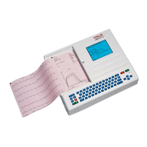
Operating Elements Introduction The CARDIOVIT AT-2plus is a 6-channel ECG recorder with all (12) ECG signals simultaneously processed to provide instant ECG recordings. Two automatic recording modes can be individually preset to enable one button ECG recording of preferred print formats. -
Page 6: Location & Power
Potential Equalisation If the AT-2plus is used in conjunction with other patient connected equipment, we recommend that the potential equalisation stud on the rear of the unit is connected to the hospital/ building common ground with the yellow/green ground cable (Part-no. -
Page 7: The Keyboard
SCHILLER AT-2plus 6-Channel ECG Unit Chapter 1 SERVICE HANDBOOK Issue d May 2002 Operating Elements The Keyboard Page 1.4... - Page 8 In the `Born` (date of birth field), only the patients year of birth need be entered if desired. When two digits are entered (patients year of birth), the AT-2plus calculates the age of the patient according to the year entered. When the full DOB is entered, the age is calculated precisely.
-
Page 9: Lcd Screen
SCHILLER AT-2plus 6-Channel ECG Unit Chapter 1 SERVICE HANDBOOK Issue d May 2002 Operating Elements LCD Screen 1. Current Heart Rate (averaged over 4 beats and refreshed every 2 seconds). The HR is also given on a manual printout. Note that with an auto mode printout the HR is averaged over the full 10 seconds of the recording. -
Page 10: At-2Plus Short Form Operating Instructions
SCHILLER AT-2plus 6-Channel ECG Unit Chapter 1 Operating Elements SERVICE HANDBOOK Issue d May 2002 AT-2plus Short Form Operating Instructions Automatic ECG Recording • Prepare skin, hook up patient. • Switch unit on, press ON • Press and enter patient data. -
Page 11: Modes Of Operation
SCHILLER AT-2plus 6-Channel ECG Unit Chapter 1 SERVICE HANDBOOK Issue d May 2002 Operating Elements Modes of Operation Automatic Mode Automatic Mode provides a printout giving 10 seconds of ECG recording of all 12 leads with a choice of 2 different formats. -
Page 12: Automatic Mode
SCHILLER AT-2plus 6-Channel ECG Unit Chapter 1 Operating Elements SERVICE HANDBOOK Issue d May 2002 Automatic Mode In automatic mode, a full 12-lead ECG is printed in one of two predefined formats with a sensitivity of 10 mm/mV. These two formats are selected by the user to suit his specific needs and requirements. -
Page 13: Manual Mode
SCHILLER AT-2plus 6-Channel ECG Unit Chapter 1 SERVICE HANDBOOK Issue d May 2002 Operating Elements Manual Mode Manual mode provides a direct printout of the real-time ECG with full control of parameter selection. To start the manual recording of a real-time ECG, press the MANUAL Printout key... - Page 14 SCHILLER AT-2plus 6-Channel ECG Unit Chapter 1 Operating Elements SERVICE HANDBOOK Issue d May 2002 Manual Mode (cont.) Chart Speed Select speed 5, 10, 25 or 50mm/s by means of the SPEED keys: 5/10 Notes: Key 7 is a toggle key -press once and 5 is selected, press a second time and 10mm/s is selected.
-
Page 15: Settings
Example If you want to reset your AT-2plus to the basic default settings, the key sequence given on page 14 is ALT; 0; 6; 6. STOP. On the following pages the programmable parameters and the programming sequences are described in detail. - Page 16 SCHILLER AT-2plus 6-Channel ECG Unit Chapter 1 Operating Elements SERVICE HANDBOOK Issue d May 2002 Settings (cont.) The defined formats and settings for your unit can be checked as follows: ALT - 0 - 1 - 1 A printout of the defined settings will be produced and gives the following information, depending...
- Page 17 SCHILLER AT-2plus 6-Channel ECG Unit Chapter 1 SERVICE HANDBOOK Issue d May 2002 Operating Elements Settings (cont.) Interpretation settings: N/A:+/- ‘normal/abnormal’ is written (+) or suppressed (-) U:+/- ‘unconfirmed report’ is written (+) or suppressed (-) A30:+/- patient age is assumed to be < 30 (-) or >30 (+)
- Page 18 SCHILLER AT-2plus 6-Channel ECG Unit Chapter 1 Operating Elements SERVICE HANDBOOK Issue d May 2002 Settings (cont.) Language The language can only be set with the SWUP program. User Identification The user identification is printed on all recordings. The user ID can be the department, doctor or hospital etc.
- Page 19 SCHILLER AT-2plus 6-Channel ECG Unit Chapter 1 SERVICE HANDBOOK Issue d May 2002 Operating Elements Settings (cont.) Filters There are three different filters which can be set individually as follows: • Baseline filter • Mains filter • Myogram filter Baseline Filter The digital Baseline filter suppresses excessive baseline drifts.
- Page 20 SCHILLER AT-2plus 6-Channel ECG Unit Chapter 1 Operating Elements SERVICE HANDBOOK Issue d May 2002 Settings (cont.) Myogram Filter The Myogram filter suppresses disturbances caused by strong muscle tremor. The set value will be the new upper limit of the frequency range as soon as the FILTER key is pressed on or programmed as default when the unit is switched on.
- Page 21 All ECG traces are centred dynamically for optimal use of paper width. Auto-Centering OFF ECG traces are set to a fixed baseline position and may possibly overlap. The Standard and Cabrera lead groups available for the AT-2plus are: Lead Groups Standard Cabrera -aVR...
- Page 22 SCHILLER AT-2plus 6-Channel ECG Unit Chapter 1 Operating Elements SERVICE HANDBOOK Issue d May 2002 Settings (cont.) Acoustic QRS Indication The acoustic QRS beep can be switched on or off at any time by pressing the QRS key Time / Date...
-
Page 23: Automatic Mode (Ecg) Settings
Operating Elements Automatic Mode (ECG) Settings Two separate Auto formats can be defined for the AT-2plus. When defining auto format 1 the key sequence ALT `1` precedes the setting. When defining auto format 2 the key sequence ALT `2` precedes the setting. - Page 24 SCHILLER AT-2plus 6-Channel ECG Unit Chapter 1 Operating Elements SERVICE HANDBOOK Issue d May 2002 Automatic Mode (ECG) Settings (cont.) Average Cycles The Average cycles are defined as follows: Note: Lead selection for the rhythm lead(s) are defined on page 25.
- Page 25 Confirm the selection by pressing the STOP key STOP Full details of the interpretation option are given in the SCHILLER ECG Measurement and Interpretation booklet (Art. No. 2.510 179). Interpretation Settings (C version only) The interpretation settings enable the user to determine whether or not certain comments will be added to the interpretation statements on the ECG printout.
- Page 26 SCHILLER AT-2plus 6-Channel ECG Unit Chapter 1 Operating Elements SERVICE HANDBOOK Issue d May 2002 Automatic Mode (ECG) Settings (cont.) Selecting Rhythm Leads The rhythm leads are printed out as defined. Two separate rhythm leads can be selected. The following formats can be set:...
-
Page 27: Memory And Data Transmission Option
SCHILLER AT-2plus 6-Channel ECG Unit Chapter 1 SERVICE HANDBOOK Issue d May 2002 Operating Elements Memory and Data Transmission Option WARNINGS & CAUTIONS WHEN NON-MEDICAL DEVICES ARE CONNECTED TO THE RS-232 INTERFACE ENSURE THAT BOTH UNITS ARE SECURELY CONNECTED TO THE SAME EARTH POTENTIAL. -
Page 28: Erasing Memory Files
LINE transmission; sending over the telephone system requires a modem and this form of sending is termed MODEM. Transmission Settings The speed settings options for the AT-2plus are as follows: Serial Communication Interface Transmission Entry Key Sequence... -
Page 29: Modem Transmission
Check all settings in the SEMACOMM program (baud rate; parity - none; stop bit - 2; time between blocks, records - 100ms). • Check that the transmission speed is the same in both the AT-2plus and the SEMACOMM program. •... -
Page 30: Line Transmission
Check all settings in the SEMACOMM program (baud rate; parity - none; stop bit - 2; time between blocks, records - 100ms). • Check that the transmission speed is the same in both the AT-2plus and the SEMACOMM program. •... -
Page 31: Software Updating Via Rs-232
SWUP Programme for Win 95 ( 2 disks or Zip-file from Mailbox) Procedure 1. Connect the AT-2plus Memory with the RS-232 cable to any free COM port on your PC 2. Switch the PC ON and go to Win 95. -
Page 32: Care & Maintenance
CLEANING LIQUID OR STERILIZE WITH HOT WATER, STEAM, OR AIR. The casing of the AT-2plus can be cleaned with a soft damp cloth on the surface only. Where necessary a domestic non-caustic cleaner can be used for grease and finger marks. - Page 33 SCHILLER AT-2plus 6-Channel ECG Unit Chapter 1 SERVICE HANDBOOK Issue d May 2002 Operating Elements Care & Maintenance (cont.) Cleaning the Patient Cable Align the leads in such a way as to prevent anyone stumbling over them or any damage caused by the wheels of instrument trolleys.
-
Page 34: Replacing The Recording Paper
Return the paper tray cover in position and press firmly until secure. • Press the STOP key to transport the paper to the start position. Note: SCHILLER can only guarantee perfect printouts when SCHILLER original chart paper or chart paper of the same quality is used. Page 1.31... -
Page 35: Thermal Paper Handling
Operating Elements Thermal Paper Handling The thermal paper used in the AT-2plus requires slightly different handling to normal paper as it can react with chemicals and to heat. However, when the following points are remembered, the paper will give reliable results: The following points apply to both storage, and when archiving the results. - Page 36 SCHILLER AT-2plus 6-Channel ECG Unit Chapter 2 SERVICE HANDBOOK Issue d May 2002 Functional Overview Chapter 2 Functional Overview Contents Introduction MK 14 - 10 Main Board Power Supply Program and ECG Memory Serial EEPROM Thermal Print Head Controller Printer Timing...
-
Page 37: Introduction
SERVICE HANDBOOK Issue d May 2002 Introduction This chapter provides a functional overview of the AT-2plus electronics. The aim of this overview is to enable the service engineer to identify processing paths in order to help identify possible faulty modules. A functional block diagram supports the text. - Page 38 SCHILLER AT-2plus 6-Channel ECG Unit Chapter 2 SERVICE HANDBOOK Issue d May 2002 Functional Overview Page 2.3...
-
Page 39: Mk 14 - 10 Main Board
Chapter 2 SCHILLER AT-2plus 6-Channel ECG Unit Functional Overview SERVICE HANDBOOK Issue d May 2002 MK 14 - 10 Main Board Power Supply The mains supply is full wave rectified to produce an unregulated dc supply of approximately 30 V (+U). This voltage is used by a switched voltage generator to produce +UD (13.5V). +UD charges the battery when mains is connected. -
Page 40: Power On Reset
SCHILLER AT-2plus 6-Channel ECG Unit Chapter 2 SERVICE HANDBOOK Issue d May 2002 Functional Overview MK 14-10 Main Board (cont.) Power On Reset The Power on reset circuit controls the master reset of the CPU. This circuit has two functions as follows: •... -
Page 41: Mk 14-11 Rs-232 Interface Board
/ serial and serial / parallell conversion for the transmission and reception of data and provide signal level compatibility with RS-232 standard. External Modem An external modem can be connected to the RS-232 output from the AT-2plus and be used for transmitting memory contents over a telephone line. Page 2.6... -
Page 42: Top Assembly
SCHILLER AT-2plus 6-Channel ECG Unit Chapter 2 SERVICE HANDBOOK Issue d May 2002 Functional Overview Top Assembly LCD Screen The LCD power supply produces the high voltage for the LCD backlight and the contrast voltage. The ECG signals are stored in a video RAM and the LCD controller converts the data to the proper form for the LCD screen. - Page 43 Chapter 2 SCHILLER AT-2plus 6-Channel ECG Unit Functional Overview SERVICE HANDBOOK Issue d May 2002 Page 2.8...
- Page 44 SCHILLER AT-2plus 6-Channel ECG Unit Chapter 3 SERVICE HANDBOOK Issue d May 2002 Fault Diagnosis Chapter 3 Fault Diagnosis Contents Introduction General Check Procedures Printer Check Print Head Alignment and Print Head Tension RS-232 Test with Test Plug Memory and Data Transmission Check...
-
Page 45: Introduction
SERVICE HANDBOOK Issue d May 2002 Introduction The AT-2plus is designed to be simple to use and simple to service: the service philosophy of the AT-2plus is module replacement and not board repair. The purpose of this chapter is to provide fault-finding procedures that will quickly and efficiently identify a fault to a specific module. -
Page 46: General Check Procedures
AT-2plus functional areas. The instructions given here are guides to the basic functions. If more operating information is required (general settings, comprehensive menu guides etc.) please refer to Chapter 1 in this publication or the relevant User Manual for the software version applicable. -
Page 47: Printer Check
Chapter 3 SCHILLER AT-2plus 6-Channel ECG Unit Fault Diagnosis SERVICE HANDBOOK Issue d May 2002 Printer Check To check the printer and to ensure that every pixel is operational, a built-in printer test is provided. To carry out the printer check press: ALT - MAN START A test printout is given. -
Page 48: Test With Test Plug
To carry out this test proceed as follows: Note: If the SCHILLER test plug is not available a test plug can easily be fabricated from a standard 9-pin D-type connector (female). Shortcircuit the following pins: •... -
Page 49: Memory And Data Transmission Check
• An RS-232 cable assembly, Art.No. 2.310 159 for connecting the RS-232 interface on the AT-2plus with the COM port of the PC. • A patient simulator attached to the patient connector on the AT-2plus. Test Procedure Command Screen Display... - Page 50 SCHILLER AT-2plus 6-Channel ECG Unit Chapter 4 SERVICE HANDBOOK Issue d May 2002 Module Removal and Replacement Chapter 4 Module Removal and Replacement Contents Introduction Safety Notices Physical Overview Exploded View Base Assembly and Printer Exploded View Paper Feed Opening and Closing the Case Printer Tray Assembly and Thermal printer 4.10...
- Page 51 Chapter 4 SCHILLER AT-2plus 6-Channel ECG Unit Module Removal and Replacement SERVICE HANDBOOK Issue d May 2002 Remove top assembly In Base assembly access to : Mains trans- Paper tray Board Battery former and assembly MK 14-10 pack connector and motor...
-
Page 52: Introduction
SCHILLER AT-2plus 6-Channel ECG Unit Chapter 4 SERVICE HANDBOOK Issue d May 2002 Module Removal and Replacement Introduction This Chapter provides an overview of the procedures to remove and replace the modules that are spared at service level. The instructions given in this chapter are autonomous, with each module containing the following: •... -
Page 53: Safety Notices
TOP ASSEMBLY REMOVED AND WITH MAINS CONNECTED. WHEN CARRYING OUT THESE PROCEDURES BEWARE THAT POTENTIALLY LETHAL VOLTAGES ARE PRESENT. CAUTIONS THE AT-2PLUS CONTAINS STATIC SENSITIVE CMOS COMPONENTS; OBSERVE ANTISTATIC PRECAUTIONS: WHEN CARRYING OUT ANY MAINTENANCE PROCEDURES ALWAYS PLACE THE UNIT ON AN EARTHED ANTISTATIC MAT. -
Page 54: Physical Overview
Module Removal and Replacement Physical Overview The AT-2plus unit is enclosed in a two part, medical standard, moulded plastic case. The top part contains the keyboard and the LCD screen with the base section containing all the electronics of the unit, the RS-232 interface, the thermal printer, the paper tray, the battery and mains transformer. -
Page 55: Exploded View Base Assembly And Printer
Chapter 4 SCHILLER AT-2plus 6-Channel ECG Unit Module Removal and Replacement SERVICE HANDBOOK Issue d May 2002 Exploded View Base Assembly and Printer Page 4.6... -
Page 56: Exploded View Paper Feed
SCHILLER AT-2plus 6-Channel ECG Unit Chapter 4 SERVICE HANDBOOK Issue d May 2002 Module Removal and Replacement Exploded View Paper Feed Page 4.7... -
Page 57: Opening And Closing The Case
Prerequisites • The unit must be placed on an antistatic mat and antistatic precautions observed when any maintenance is carried out on the AT-2plus. The room temperature should be between 18 and 28 degrees. • THE WARNINGS AND CAUTIONS AT THE BEGINNING OF THE CHAPTER MUST BE OBSERVED. - Page 58 SCHILLER AT-2plus 6-Channel ECG Unit Chapter 4 SERVICE HANDBOOK Issue d May 2002 Module Removal and Replacement Opening and Closing the Case Top Assembly Replacement To replace the Top Assembly proceed as follows: 1. Check that all boards and components are firmly secured. Check for loose screws. Ensure that no screws or foreign bodies are loose in the bottom of the case.
-
Page 59: Printer Tray Assembly And Thermal Printer
Chapter 4 SCHILLER AT-2plus 6-Channel ECG Unit Module Removal and Replacement SERVICE HANDBOOK Issue d May 2002 Printer Tray Assembly and Thermal printer Prerequisite • The Warnings and Cautions at the beginning of the Chapter must be observed. • The Top Assembly must be removed as detailed previously. All external cable assemblies must be disconnected. -
Page 60: Thermal Printer Replacement
SCHILLER AT-2plus 6-Channel ECG Unit Chapter 4 SERVICE HANDBOOK Issue d May 2002 Module Removal and Replacement Printer Tray Assembly and Thermal printer Thermal Printer Replacement. To replace the Thermal Printer proceed as follows: 1. Position the Printer in the paper tray/print assembly so that the printer mounting plate lips slot into the dedicated cutouts in the assembly;... -
Page 61: Main Board Mk
Chapter 4 SCHILLER AT-2plus 6-Channel ECG Unit Module Removal and Replacement SERVICE HANDBOOK Issue d May 2002 Main Board MK 14 - 10 Prerequisite • The Warnings and Cautions at the beginning of the chapter must be observed. • The top assembly must be removed and all external cable assemblies disconnected. -
Page 62: Battery Pack
SCHILLER AT-2plus 6-Channel ECG Unit Chapter 4 SERVICE HANDBOOK Issue d May 2002 Module Removal and Replacement Battery Pack Prerequisite • The Warnings and Cautions at the beginning of the Chapter must be observed. • The Top Assembly must be removed and all external cable assemblies disconnected. -
Page 63: Keyboard
Chapter 4 SCHILLER AT-2plus 6-Channel ECG Unit Module Removal and Replacement SERVICE HANDBOOK Issue d May 2002 Keyboard The keyboard comes as a complete assembly with the top casing. The part number of the keyboard is given in Chapter 6. -
Page 64: Lcd Screen Board
SCHILLER AT-2plus 6-Channel ECG Unit Chapter 4 SERVICE HANDBOOK Issue d May 2002 Module Removal and Replacement LCD screen board Prerequisite • The Warnings and Cautions at the beginning of the Chapter must be observed. • The Top Assembly must be removed as detailed previously. All external cable assemblies must be disconnected. -
Page 65: Rs-232 Serial Interface Board Mk
Chapter 4 SCHILLER AT-2plus 6-Channel ECG Unit Module Removal and Replacement SERVICE HANDBOOK Issue d May 2002 RS-232 Serial Interface Board MK 14 - 11 Prerequisite • The Warnings and Cautions at the beginning of the Chapter must be observed. - Page 66 SCHILLER AT-2plus 6-Channel ECG Unit Chapter 5 SERVICE HANDBOOK Issue d May 2002 Adjustments Chapter 5 Adjustments Contents Introduction Safety Notices and Conditions Conditions Test Equipment Proprietary Test Equipment/Tools Main Board MK 14-10 Adjustment locations Battery Charge Voltage Precautions and Requirements...
-
Page 67: Introduction
Specific warnings and cautions are given in the text where applicable. The part numbers for all replaceable modules are given in Chapter 6. The AT-2plus has the following adjustments: • Battery Charge Voltage (VR1 on the main board MK 14-10) •... -
Page 68: Safety Notices And Conditions
USE FORCE. NEVER STRAIN THE CABLE ASSEMBLIES. THE PROCEDURAL STEPS GIVEN FOR EACH MODULE MUST BE FOLLOWED IN THE ORDER GIVEN. THE OUTER SURFACES OF THE AT-2PLUS ARE SUSCEPTIBLE TO ABRASION DAMAGE. TO PREVENT SCRATCHING, ALWAYS PLACE ON A SOFT, NON-ABRASIVE CLOTH. -
Page 69: Test Equipment
ECG Simulator, e.g. Phantom 320 • Oscilloscope • Digital Multimeter • Standard tool kit with a selection of cross-bladed, flat-bladed and posi-drive screwdrivers, pliers and general tools • SCHILLER 10 lead patient cable Number 2.400070 (2. 400071 for USA) Page 5.4... -
Page 70: Main Board Mk 14-10 Adjustment Locations
SCHILLER AT-2plus 6-Channel ECG Unit Chapter 5 SERVICE HANDBOOK Issue d May 2002 Adjustments Main Board MK 14-10 Adjustment locations Page 5.5... -
Page 71: Battery Charge Voltage
Battery Charge Voltage Precautions and Requirements The unit must be placed on an antistatic mat and antistatic precautions observed when any maintenance is carried out on the AT-2plus. The room temperature should be between 18 and 28 degrees. Tools and Equipment •... -
Page 72: Paper Mark Detector Check
SCHILLER AT-2plus 6-Channel ECG Unit Chapter 5 SERVICE HANDBOOK Issue d May 2002 Adjustments Paper mark Detector Check Tools, Equipment and Material • Digital voltmeter • Small flat bladed screwdriver • 70% alcohol solution and clean lint free cloth Procedure To adjust the paper-mark Schmitt trigger sensitivity proceed as follows: •... -
Page 73: Ecg Amplifier +2V, -2V And Pwm Ramp Time Adjustment
• DISCONNECT THE MAINS SUPPLY CAUTIONS THE AT-2PLUS CONTAINS STATIC SENSITIVE CMOS COMPONENTS; OBSERVE ANTISTATIC PRECAUTIONS . PLACE THE UNIT ON AN EARTHED ANTISTATIC MAT. PERSONNEL MUST BE EARTHED WHEN HANDLING THE UNIT. EXERCISE CARE WHEN REMOVING AND REPLACING CONNECTORS. NEVER USE FORCE. -
Page 74: Ecg Amplifier Reference Voltage
SCHILLER AT-2plus 6-Channel ECG Unit Chapter 5 SERVICE HANDBOOK Issue d May 2002 Adjustments ECG Amplifier reference voltage • Switch the unit on and measure the voltage difference between the +2V reference and the - 2V reference on pins 1 and 7 of operational amplifier U5. Adjust trimmer VR2 to achieve a voltage difference of 4000 mV ±2mV. -
Page 75: Service Screen
Chapter 5 SCHILLER AT-2plus 6-Channel ECG Unit Adjustments SERVICE HANDBOOK Issue d May 2002 Service Screen The service screen provides information of the patient cable and electrodes and gives the value of certain reference voltages and important internal offset values. These values are for information only. - Page 76 SCHILLER AT-2plus 6-Channel ECG Unit Chapter 5 SERVICE HANDBOOK Issue d May 2002 Adjustments Service Screen (cont.) Electrode dc offset This gives the voltage drop in the patient cable and can indicate any faults in the patient cable or patient electrode.
-
Page 77: Software Options / Updates
Acceptance of the code is indicated by a series of beeps. CAUTION MORE THAN 10 ATTEMPTS TO ENTER THE INCORRECT CODE BLOCKS THE UNIT Installing Software Updates To update the operating software in the AT-2plus see instructions in Chapter 1 of this book. Page 5.12... - Page 78 SCHILLER AT-2plus 6-Channel ECG Unit Chapter 6 SERVICE HANDBOOK Issue d May 2002 Spare Parts Chapter 6 Spare Parts Contents Ordering Information Service Department Spare Parts Page 6.1...
- Page 79 Your local representative stocks all the disposables and accessories available for the AT-2plus. In case of difficulty or to obtain the address of your local dealer, please contact the head office. Our staff will be pleased to help process your order or to provide any details for all SCHILLER products.
- Page 80 SCHILLER AT-2plus 6-Channel ECG Unit Chapter 6 SERVICE HANDBOOK Issue d May 2002 Spare Parts Spare Parts Description Part Number Mikroprocessor and power supply board MK 14-10 3.248 3BC Keyboard MK 14-3B 3.248 2BA RS-232 Interface board MK 14-11 3.248 5BA LCD Module 4.600 062...
- Page 81 Chapter 6 SCHILLER AT-2plus 6-Channel ECG Unit Spare Parts SERVICE HANDBOOK Issue d May 2002 Page 6.4...
- Page 82 SCHILLER AT-2plus 6-Channel ECG Unit Chapter 7 SERVICE HANDBOOK Issue d May 2002 Technical Data Chapter 7 Technical Data Contents Technical Data Available Configurations Page 7.1...
- Page 83 Chapter 7 SCHILLER AT-2plus 6-Channel ECG Unit Technical Data SERVICE HANDBOOK Issue d May 2002 Technical Data Technical data subject to change without notice. Dimensions: 400 x 330 x 100 mm Weight: 5.0 kg ( 5.35 kg with full paper tray)
- Page 84 25 to 95% (non condensing) Atmospheric pressure: 700 to 1060 hPa Control Panel: Rubber keys Available Configurations The CARDIOVIT AT-2plus is available in several versions: Standard Version: Unit with ECG recording and printout capabilities. Version C: Unit with additional ECG Interpretation program (including measurements).
- Page 85 Chapter 7 SCHILLER AT-2plus 6-Channel ECG Unit Technical Data SERVICE HANDBOOK Issue d May 2002 Page 7.4...
- Page 86 SCHILLER AT-2plus 6-Channel ECG Unit Chapter 8 SERVICE HANDBOOK Issue d May 2002 Glossary Chapter 8 Glossary Contents Introduction Acronyms Page 8.1...
- Page 87 The following list provides a glossary of the important signals and acronyms used in the circuit diagrams for the SCHILLER instruments. They will not all apply to the AT-2plus Memory. Only abbreviations that are specific to SCHILLER equipment are included here. General electrical and electronic abbreviations are not included.
- Page 88 SCHILLER AT-2plus 6-Channel ECG Unit Chapter 8 SERVICE HANDBOOK Issue d May 2002 Glossary Acronyms ..OS Offset signal (on the ECG amplifier). A(1...n) CPU Address Bus ALBEEP Alarm beeper signal to the audio amplifier. The frequency of this signal is about 1000 Hz.
- Page 89 Chapter 8 SCHILLER AT-2plus 6-Channel ECG Unit Glossary SERVICE HANDBOOK Issue d May 2002 Acronyms DTACK Transfer data acknowledge. Bus signal to acknowledge transfer of data. Outgoing serial data, turns modem ON. ECGI ECG in - serial ECG data to the CPU sent over the optical interface.
- Page 90 Motor ON - printer motor enable signal. NWTZ Mains supply. Non-maskable interrupt - interrupt for U47 (Schiller gate array) activated by the reset button. Off signal from the OFF key to switch off the power supply. Control signal derived from FLM (unity waveform 1/2 FLM frequency).
- Page 91 Upper column address strobe (for dynamic RAM). UD1, UD2 Upper data strobe - used for generating UOE and UWE. Upper data strobe - used on the Schiller gate array. UOE, USRAM Upper output enable - for static RAM. Page 8.6...
- Page 92 SCHILLER AT-2plus 6-Channel ECG Unit Chapter 8 SERVICE HANDBOOK Issue d May 2002 Glossary Acronyms Voltage rectified from the mains input and regulated to approximately +15 V. Upper write enable. Unregulated dc supply from mains (approximately 30V). +UBU Back-up voltage for the real time clock and static RAM.
- Page 93 Chapter 8 SCHILLER AT-2plus 6-Channel ECG Unit Glossary SERVICE HANDBOOK Issue d May 2002 Page 8.8...
Need help?
Do you have a question about the AT-2plus and is the answer not in the manual?
Questions and answers