Advertisement
Quick Links
Advertisement

Subscribe to Our Youtube Channel
Related Manuals for Okolab H201-ENCLOSURE-DMi8-LASERSAFE-158


Summary of Contents for Okolab H201-ENCLOSURE-DMi8-LASERSAFE-158
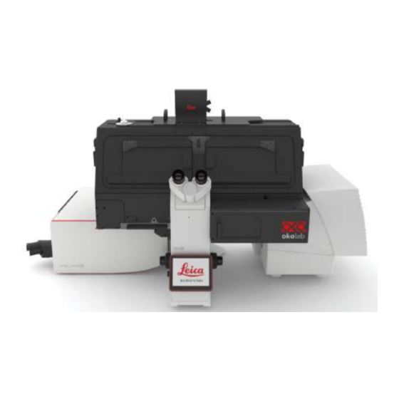
- Page 1 Assembly Manual H201-ENCLOSURE-DMi8-LASERSAFE-158 Leica line item - 158206045...
- Page 2 Unboxing: BOX-1 Accessories ⑧ ① ② ③ ④ ⑤ ⑧ ⑥ ⑦ Item Label Back Cube Fixing Plate Enclosure Left-2-AFC Left Base Left-1 Left-1-AFC Right – Left handle cover Led foot pedal and power supply...
- Page 3 Unboxing: BOX-2 Accessories ⑨ ⑩ ⑪ ① ⑫ ⑧ ② ⑦ ③ ⑥ ④ ⑤ Item Label Item Label Right Base CV-A 2H2P Base Right Base CV-B 2P2P Base Right Base CV 2P2P Back-CV 4Tune Base 2H2P Back-CV 2H Back-CV Right Base Manual-CV 2H Base...
- Page 4 Step. 1 Place the “Fixing Plate” CBSM8-12-2...
- Page 5 Step. 2 Remove the stage and the camera on the pillar...
- Page 6 Step. 3 Place the “Enclosure” on the “Fixing Plate” 2x CRKB3_15 Screws with Knurled Resin Heads M3 x 15mm...
- Page 7 Cage Fastening Step. 4 On the back side of the front panel there is a plastic insert. This insert could be pushed on the microscope surface to fix the enclosure to the microscope To fix the enclosure to the cage use the screw as shown...
- Page 8 Step. 5 Place the “Back Cube” CRKB3-12 Screws with Knurled Resin Heads M3 x 12mm...
- Page 9 Step. 6 Place the “Left Base”...
- Page 10 Place the “Left-1” if the microscope is without Step. 7 AFC module M 3x6 Left-1 TCCE-DIN912-ISO4762-M-A2...
- Page 11 Step. 8 Place the “Left-1-AFC”e “Left-2-AFC” if the microscope is with AFC module Captive screw M3 x 12mm Left-2-AFC Left-1-AFC...
- Page 12 Right base configuration 4Tune Right Base 4Tune Base Config. 1 2ch HyD RLD detector Right Base 2H Base Config. 2 2ch HyD RLD detector (front position) Right Base 2H2P Base plus 2ch PMT (rear position) Config. 3 2P2P Base Right Base 2ch PMT plus 2ch PMT Config.
- Page 13 Config. 1 CRKB3-12 Screws with Knurled Resin Heads M3 x 12mm Right Base CV CRKB3-12 Screws with Knurled Resin Heads M3 x 12mm...
- Page 14 Config. 1 Manual 3-plate stage 11522076 Step.2 Step.1 Step.4 Step.3...
- Page 15 Place the “Manual-CV” Bottom view...
- Page 16 Config. 2 4x M3x12 3x M3x6 TPS-CROCE-DIN-965-A2-M TPS-CROCE-DIN-965-A2-M 2H Base 4Tune Base...
- Page 17 Step.1 Step.2 Step. 3 Step.4 CRKB3-12 Screws with Knurled Resin Heads ,M3 x 12mm Step. 5 5x M3x8 TPS-CROCE- DIN-965-A2-M 2H Back-CV...
- Page 18 Config. 3 4x M3x12 3x M3x6 TPS-CROCE-DIN-965-A2-M TPS-CROCE-DIN-965-A2-M 2H2P Base 4Tune Base...
- Page 20 CRKB3-12 Screws with Knurled Resin Heads M3 x 12mm 2H2P Back-CV 5x M3x6 TPS-CROCE-DIN-965-A2-M...
- Page 21 Right Base CV configuration Scanning stage 11522100/158004141 Right Base CV-A Right Base CV-B (stage 11522100/158004141)
- Page 22 Config. 4 4x M3x12 3x M3x6 TPS-CROCE-DIN-965-A2-M TPS-CROCE-DIN-965-A2-M 2P2P Base 4Tune Base...
- Page 23 2P2P Back-CV 4x M3x6 TPS-CROCE-DIN-965-A2-M...
- Page 24 Place the stage and the camera on the pillar Remove the front panel Place the stage and the camera on the pillar...
Need help?
Do you have a question about the H201-ENCLOSURE-DMi8-LASERSAFE-158 and is the answer not in the manual?
Questions and answers