Table of Contents
Advertisement
Quick Links
Advertisement
Table of Contents

Subscribe to Our Youtube Channel
Related Manuals for Okolab H301-MCL-Z100/500


Summary of Contents for Okolab H301-MCL-Z100/500
- Page 1 User Manual H301-MCL-Z100/500 Rev 03 H301-MCL-Z100/500 Compatible with the following XY stages Compatible with the following Okolab Controllers • • Mad City Labs: Z100/500 H301-T-BL-PLUS • UNO-T • UNO-T-H-PREMIXED • UNO-T-H-CO2 www.oko-lab.com...
-
Page 2: Table Of Contents
User Manual H301-MCL-Z100/500 Rev 03 Index Components and dimensions....................3 Available Sample Holders ....................... 3 Available Lids ........................4 3.1 Sliding lid .......................... 5 3.2 Koehler Lid ........................6 3.3 Injection Lid ........................6 3.4 Laser Interlock Lid ....................... 7 Insertion of the Sample Feedback Temperature Sensor .............. -
Page 3: Components And Dimensions
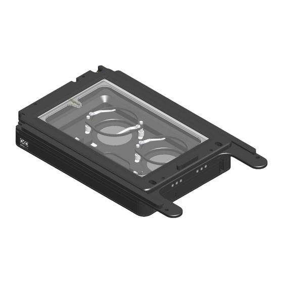
Sample Holder-Order Separately Chamber Riser Chamber top view Chamber Base Figure 1. H301-MCL-Z100/500. Components and Dimensions. 2. Available Sample Holders The following sample holders are available. NOTE: Please contact info@oko-lab.com if you cannot find the sample holder you are looking for. We are constantly adding new inserts to the list. -
Page 4: Available Lids
24-well NUNC/GREINER plates 48MW 48-well plates 96MW 96-well plates. *Includes MW-OIL MW-OIL Open frame to image multi well plates with oil immersion objectives Figure 2.Available sample holders. 3. Available Lids The following heated glass Lids are available for H301-MCL-Z100/500: www.oko-lab.com... -
Page 5: Sliding Lid
User Manual H301-MCL-Z100/500 Rev 03 • H301-SLIDING-LID: For easy sample loading and pipetting – Included in code H301-MCL-Z100/500. • H301-KOEHLER-LID*: Reduces chamber height to 22 mm and allows imaging under Koehler illumination • H301-INJECTION-LID*: Heated glass lid with two small openings (sealed with flexible plastic) allowing injec- tion or permanent access to the sample. -
Page 6: Koehler Lid
Chamber top view Figure 5. H301-MCL-Z100/500 + H301-KOEHLER-LID Injection Lid The Injection Lid is a heated glass lid with two small openings sealed with flexible plastic allowing injection or perma- nent access to the sample. -
Page 7: Laser Interlock Lid
Chamber top view Figure 6. H301-MCL-Z100/500+ H301-INJECTION-LID Laser Interlock Lid The Laser Interlock Lid is a heated glass lid with a safety switch connecting to the laser controller. It automatically turns the laser off when the lid is lifted. -
Page 8: Insertion Of The Sample Feedback Temperature Sensor
H301-MCL-Z100/500 Rev 03 4. Insertion of the Sample Feedback Temperature Sensor Insert the Sample Feedback Temperature Sensor through the dedicated opening located in the H301-MCL-Z100/500 (see Figure 8, Frontal and 3D views). Temperature Sensor dedicated opening Temperature Sensor dedicated opening 1.Frontal view... -
Page 9: Working With 35 Or 60 Mm Petri Dish - Spacing Rings And Magnetic Locks
User Manual H301-MCL-Z100/500 Rev 03 6. Working with 35 or 60 mm Petri Dish – Spacing Rings and Magnetic Locks Magnetic locks prevent movement of 35 and 60 mm dishes inside the sample holder. Figure 10 illustrates the available magnetic locks for 35 and 60 mm dishes. Threaded magnetic posts allow adjusting holder’s height. - Page 10 User Manual H301-MCL-Z100/500 Rev 03 Grainer-Petri35x10 Ibidi μ-Dish 35 mm-low BD Falcon-35x10 Willco-35x10 Corning-35x10 mm MatTek-P35G-X14-X Figure 12. Ring selection scheme for 35 mm dish. Ibidi μ-Dish 50 mm-low MatTek-P50G-X30-X BD Falcon-60x10 Grainer - Petri 60x15 Corning-60x15 mm Willco 60x15 Figure 13.
-
Page 11: Working With 1X3'' And 1X2'' Chamber Slides - Magnetic Locks
User Manual H301-MCL-Z100/500 Rev 03 7. Working with 1x3’’ and 1x2’’ chamber slides - magnetic locks Magnetic locks prevent movement of 1’’x 3’’ and 1’’x 2’’ chamber slides inside of the sample holder. NOTE: Magnetic locks are included with sample holder. -
Page 12: Working With Mw Plates - Magnetic Locks And Chamber Riser
A single silicon tubing carries output gas from the Okolab Gas Controller to the H301-MCL-Z100/500. Silicon tubing connects to a gas input - brass opening - located on a corner of the H301-MCL-Z100/500. See Figure 18. Connect by gently pushing silicon tubing onto brass opening. -
Page 13: Working With Perfusion
10. Working with Perfusion The Chamber Riser included with H301-MCL-Z100/500 features 12 perfusion holes for the insertion of perfusion tubing up to 2.5 mm in outer diameter. To lock the Chamber Riser into the base use a 1.5mm Allen key to secure the 4 GUTB2-2,5-6 screws as shown in Figure 19. - Page 14 User Manual H301-MCL-Z100/500 Rev 03 Perfusion dedicated opening 1.Frontal view 2.3D view Figure 20. Perfusion. Figure 21. How to access the perfusion holes. www.oko-lab.com...
-
Page 15: Microfluidic-C-Riser (Optional)
The MICROFLUIDIC-C-RISER is a chamber riser with 19x3 mm windows (on the two short sides) to allow insertion of microfluidic tubings. Windows are magnetically closed. Compatible with most of H201 and H301 Okolab chambers. Thickness of this chamber riser is 8mm (2mm more than default chamber riser). Requires Koehler lid and single ac- commodation specimen holders. -
Page 16: Connection Of The Chamber With Z Piezo Stage
User Manual H301-MCL-Z100/500 Rev 03 11. Connection of the Chamber with Z Piezo stage Follow the steps shown in the images of Figure 23 and listed below in order to correctly connect the chamber with Z piezo stage. Place the chamber on the stage and tighten 2 captive screws (See Image 2 Figure 23). Captive screws housings are indicated with letter B in Image 2 of Figure 23 Use a 1.5mm metric Allen Wrench to tighten one of the two captive screws (B in Image 3) while keeping the... -
Page 17: Cleaning
User Manual H301-MCL-Z100/500 Rev 03 12. Cleaning • Turn the system off and pull the mains plug out the socket • Remove the lid from the chamber main body, and keep it separate from the chamber main body while the chamber cools down.
Need help?
Do you have a question about the H301-MCL-Z100/500 and is the answer not in the manual?
Questions and answers