
Subscribe to Our Youtube Channel
Related Manuals for Advantech PCIE-1840


Summary of Contents for Advantech PCIE-1840
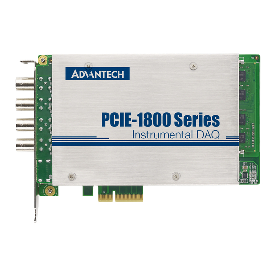
- Page 1 User Manual PCIE-1840 4-ch 16Bit 125 MS/s High-Speed Data Acquisition PCI Express Card...
- Page 2 No part of this manual may be reproduced, copied, translated or transmitted in any form or by any means without the prior written permission of Advantech Co., Ltd. Information provided in this manual is intended to be accurate and reliable. How- ever, Advantech Co., Ltd.
- Page 3 This product has passed the CE test for environmental specifications when shielded cables are used for external wiring. We recommend the use of shielded cables. This kind of cable is available from Advantech. Please contact your local supplier for ordering information.
- Page 4 PCIE-1840 User Manual...
-
Page 5: Table Of Contents
Device Auto Installation (Recommended)........9 Device Setup & Configuration ..............9 Figure 2.1 The Device Setting of PCIE-1840......9 Figure 2.2 The Device Setting page .......... 10 Figure 2.3 The Device Testing of PCIE-1840 ......11 Chapter Signal Connections ......13 Overview .................... - Page 6 AI Input Bandwidth and Settling.............. 27 A.6.1 Tunable Capacitor for One-tenth Voltage Divider in 1Mohm ..27 Figure A.3 PCIE-1840 one-tenth divider Circuit......27 Figure A.4 Without capacitors compensation, the settling time is quite slow ..............28 Figure A.5 With compensation, settling time is much faster ..28...
- Page 7 Chapter Introduction This chapter will provide informa- tion on the features of the PCIE- 1840 cards, a quick installation guide, together with some brief information on software and accessories. Sections include: Features Applications Installation Guide Software Overview ...
-
Page 8: Chapter 1 Introduction
1.2.2 BoardID Switch The PCIE-1840 has a built-in DIP switch that helps define each card’s ID when multi- ple PCIE-1840 cards have been installed on the same PC chassis. The BoardID set- ting function is very useful when building a system with multiple PCIE-1840 cards. -
Page 9: Installation Guide
Installation Guide Before you install your PCIE-1840 card, please make sure you have the following components: PCIE-1840 DA&C card PCIE-1840 Startup Manual Driver software Advantech DAQNavi SDK and drivers (included in the companion CD-ROM) Auto-Calibration Board PCLD-8841 ... -
Page 10: Device Drivers
C++ Builder For instructions on how to begin programming works in each development tool, Advantech offers a Tutorial Chapter in the DAQNavi SDK Manual for your reference. Refer to the corresponding sections in this chapter on the DAQNavi SDK Manual to begin your programming efforts. -
Page 11: Programming With Daqnavi Device Drivers Function Library
1.6.2 Programming with DAQNavi Device Drivers Function Library Advantech DAQNavi Device Drivers offer a rich function library that can be utilized in various application programs. This function library consists of numerous APIs that support many development tools, such as Visual Studio.Net, Visual C++, Visual Basic, Delphi and C++ Builder. - Page 12 PCIE-1840 User Manual...
-
Page 13: Chapter 2 Installation
Chapter Installation... -
Page 14: Unpacking
PC or transport it elsewhere. Driver Installation We recommend you install the driver before you install the PCIE-1840 card into your system, since this will guarantee a smooth installation process. The Advantech DAQNavi Device Drivers Setup program for the PCIE-1840 card is included in the companion DVD-ROM that is shipped with your DA&C card package. -
Page 15: Device Auto Installation (Recommended)
2.2.1 Device Auto Installation (Recommended) You can install the PCIE-1840 module in any PCI Express slot on your computer. Fol- low the steps below to install the module on your system. Turn off your computer and unplug the power cord and cables. TURN OFF your computer before installing or removing any components on the computer. - Page 16 Configuring the Device Go to the Device Setting to configure your device. Here you can configure not only the Analog Input of PCIE-1840 but also Digital Input/Output. Figure 2.2 The Device Setting page PCIE-1840 User Manual...
- Page 17 After your card is properly installed and configured, you can go to the Device Test page to test your hardware by using the testing utility supplied. Figure 2.3 The Device Testing of PCIE-1840 For more detailed information, refer to the DAQNavi SDK Manual or the User Inter- face Manual in the Advantech Navigator.
- Page 18 PCIE-1840 User Manual...
-
Page 19: Chapter 3 Signal Connections
Chapter Signal Connections This chapter provides useful information about how to connect input and output signals to the PCIE-1840 cards via the I/O con- nector. Sections include: Overview Switch Settings Signal Connections Field Wiring Considerations... -
Page 20: Overview
Jumper Settings Setting the BoardID Switch (SW1) The PCIE-1840 has a built-in DIP switch (SW1), which is used to define each card's board ID. You can determine the board ID on the register as shown in Table 3.1. When there are multiple cards on the same chassis, this board ID setting function is useful for identifying each card's device number through board ID. -
Page 21: Signal Connections
Signal Connections Pin Assignment There are four BNC and one 19-pin connectors on the PCIE-1840, which connects to BNC and PCL-10119 HDMI cables. Figure 3.1 and Figure 3.2 show the pin assign- ments for the BNC and 19-pin I/O connector separately, and Table 3.1 shows its I/O connector signal description. -
Page 22: Trigger Type
3.3.2.1 Digital Trigger Connections You can configure the PCIE-1840 to trigger in response to digital signals on DTRG0 or DTRG1 pin of the HDMI connector, located on the device front panel. The trigger circuit can respond either to a rising or a falling edge. The trigger signal must comply to 3.3 V or 5 V TTL voltage levels. - Page 23 3.3.2.2 Analog Trigger You can configure the PCIE-1840 analog trigger circuitry to monitor any input chan- nel from which you acquire data. Choosing an input channel as the trigger channel does not influence the input channel acquisition capabilities. The trigger circuit generates an internal digital trigger based on the input signal and the defined trigger levels.
-
Page 24: Pcld-8841 Signal Connection
3.3.3 PCLD-8841 Signal Connection To ensure the accuracy of PCIE-1840 would not drift by time, periodical calibrations are necessary to make the performance match its specification. PCIE-1840 provides two methods for calibration, manual-calibration and self-calibration with PCLD-8841. By manual calibration, PCIE-1840 could achieve higher accuracy but it takes more time and is suitable for the users who require a single channel calibration. -
Page 25: Field Wiring Considerations
Field Wiring Considerations When you use PCIE-1840 cards to acquire data from outside, noises in the environ- ment might significantly affect the accuracy of your measurements if due cautions are not taken. The following measures will be helpful to reduce possible interference run- ning signal wires between signal sources and the PCIE-1840 card. - Page 26 PCIE-1840 User Manual...
-
Page 27: Appendix A Specifications
Appendix Specifications... -
Page 28: General Specifications
± 2 ± 2 ± 5 Noise Filter Enable Filter Disable Bandwidth (-3 dB) 40 MHz for 0.2 Vpk-pk, 20 MHz 65 MHz for others Max. Input Voltage ± 15 V Over-voltage protection 2 x FS (Full-Scale) voltage PCIE-1840 User Manual... -
Page 29: Trigger
Reference Clock Frequency 10 MHz External Reference Clock 50 Ohm input impedance External Reference Clock input Coupling External Reference Clock LVPECL Output Compatible External Reference Clock 200 Ohm, Differential Output Impedance Reference Clock output 10 MHz Frequency PCIE-1840 User Manual... -
Page 30: Dynamic Characteristics
Total Harmonic Distortion Input Impedance: 50 Input Impedance: 1M (dB)* Input Range Filter ON Filter OFF Filter ON Filter OFF ±10.0 V -71.5 -71.5 ±5.0 V -83.5 ±2.0 V -82.5 ±1.0 V -82.5 ±0.5 V -82.5 ±0.2 V -83.5 PCIE-1840 User Manual... -
Page 31: Total Harmonic Distortion Plus Noise (Thd+N)
Flatness* ** (dB) ±0.8 ±0.4 DC to 10 MHz ** Referenced to 100 kHz. A.5.7 Crosstalk Filter ON Filter OFF Crosstalk* ** (dBc) <= 80 <= 68 CH1 to CH0 at 10 MHz ** Input Amplitude: -1 dBFS PCIE-1840 User Manual... -
Page 32: Ac Coupling
A.5.8 AC Coupling -3 dB cutoff frequency : 10.6 HZ ( 1M Ohm input impedance only) Figure A.1 Magnitude response of AC coupling circuit Figure A.2 Phase response of AC coupling circuit PCIE-1840 User Manual... -
Page 33: Ai Input Bandwidth And Settling
Tunable Capacitor for One-tenth Voltage Divider in 1Mohm Figure A.3 PCIE-1840 one-tenth divider Circuit PCIE-1840 provides tunable capacitors beside each BNC connector to help compen- sate the input bandwidth of 20Vpp, 10Vpp, and 4Vpp input ranges with 1M Ohm input impedance. - Page 34 Figure A.4 Without capacitors compensation, the settling time is quite slow Figure A.5 With compensation, settling time is much faster For the users requiring high frequency applications, it’s highly recommended to select 50 Ohm input impedance to ease the known overshoot and parasitic capaci- tance issue. PCIE-1840 User Manual...
-
Page 35: Appendix B Block Diagram
Appendix Block Diagram... -
Page 36: Overview
Overview Figure B.1 Function block diagram - overview Analog Input TIS Function Figure B.2 Dual ADCs combination architecture in TIS mode PCIE-1840 User Manual... - Page 37 1840. They will lead to voltage swings in time domain and unexpected spurs in fre- quency domain. These mismatches include offset mismatch, gain mismatch, and clock phase mismatch. Though PCIE-1840 is capable to calibrate the gain error under TIS, the non-perfectly matched ADCs would still degrade the SNR ratio. Users should take this unavoidable degradation into consideration, especially in frequency domain applications.
- Page 38 No part of this publication may be reproduced in any form or by any means, electronic, photocopying, recording or otherwise, without prior written permis- sion of the publisher. All brand and product names are trademarks or registered trademarks of their respective companies. © Advantech Co., Ltd. 2015...
Need help?
Do you have a question about the PCIE-1840 and is the answer not in the manual?
Questions and answers