Table of Contents
Advertisement
Quick Links
SERVICE MANUAL
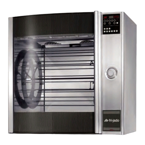
STG ROTISSERIE OVEN MODELS
MODELS
Programmable controls
Versions:
Solid Back
Pass-Through
Pass-Through with rotor button
WWW.FRIJADO.COM
This manual is prepared for the use of trained Service Technicians and should not
be used by those not properly qualified. If you have attended a trianing for this
product, you may be qualified to perform all the procedures in this manual.
This manual is not intended to be all encompassing. If you have not attended
training for this product, you should read, in its entirety, the repair procedure you
wish to perform to determine if you have the necessary tools, instruments and
skills required to perform the procedure. Procedures for which you do not have the
necessary tools, instruments and skills should be performed by a trained technician.
Reproduction or other use of this Manual, without the express written consent of
STG8 P
Model STG8 P solid back
- NOTICE -
Fri-Jado, is prohibited.
Service Manual STG8 P form 9123539 rev. 04/2014
Advertisement
Table of Contents
Troubleshooting

Related Manuals for Fri-Jado STG8 P


Summary of Contents for Fri-Jado STG8 P
- Page 1 Procedures for which you do not have the necessary tools, instruments and skills should be performed by a trained technician. Reproduction or other use of this Manual, without the express written consent of Fri-Jado, is prohibited. WWW.FRIJADO.COM Service Manual STG8 P form 9123539 rev. 04/2014...
- Page 2 Page 2 Service Manual STG8 P form 9123539 rev. 04/2014...
- Page 3 Versions Version Issue date Remarks dd/mm/yy 02/2007 01/02/2007 First release. 04/2010 01/04/2010 Textual changes. Troubleshooting adaped. 03/2014 01/03/2014 Textual changes. Electrical tests adaped. Page 3 Service Manual STG8 P form 9123539 rev. 04/2014...
-
Page 4: Table Of Contents
Technical Data ..........................6 Programming instructions for the STG8 P ....................7 Optional settings for the HR8 P ....................... 9 Removal and replacement of parts for the STG8 P ................11 Right or left side panel ........................11 Top cover ............................11 Knob ............................... - Page 5 STG8 P solid back - wiring diagram (till 31-12-2006) ..............55 STG8 P + rotor switch - circuit diagram ..................56 STG8 P + rotor switch - circuit diagram (till serial number 100044773) ........57 STG8 P + rotor switch - wiring diagram (till serial number 100044773) ........58 STG8 P + rotor switch - circuit diagram (till 31-12-2006) .............
-
Page 6: General Technical Data
GENERAL TECHNICAL DATA GENERAL TECHNICAL DATA This manual covers the STG8 P series rotisserie ovens. Ovens will also be delivered in stacked versions. • STG8 P - Oven with eight spits ( 32 to 40 chickens ) All of the information, illustrations and specifications contained in this manual are based on the latest product information available at the time of printing. -
Page 7: Programming Instructions For The Stg8 P
Temperature hold process Second grilling step First grilling step SETTING THE STG8 P When the main switch is turned to “1” the display lights up and the rotisserie is ON. Service Manual STG8 P form 9123539 rev. 04/2014 Page 7... - Page 8 8 8 8 8 0 0 4 0 perature key 8888 0030 Grilling symbol lights up Press Up or Down key Press and hold the Time Press Up or Down key Page 8 Service Manual STG8 P form 9123539 rev. 04/2014...
-
Page 9: Optional Settings For The Hr8 P
8 88 888 8 105 5 P 01 Heaters and front lamp switch off Press and hold Buzzer Rotor stops Press Down key On indicator is blinking Process time in hold Service Manual STG8 P form 9123539 rev. 04/2014 Page 9... - Page 10 • Temperature display indicates actual swtiches off temperature in the grill. Under 40°C (104°F) the display shows PRH (preheat). • When remaining time reaches 0, the process indicators and the On-indicator switches off. Page 10 Service Manual STG8 P form 9123539 rev. 04/2014...
-
Page 11: Removal And Replacement Of Parts For The Stg8 P
REMOVAL AND REPLACEMENT OF PARTS REMOVAL AND REPLACEMENT OF PARTS FOR THE STG8 P WARNING: Disconnect the electrical power to the machine at the main circuit box. Place a tag on the circuit box indica- ting the circuit is being serviced. -
Page 12: Operating Panel
3. Remove on the inside bottom of the elec- tric panel the bolt and nuts. 4. Disconnect the wiring. 5. Slide the electrical panel backwards. 6. Reverse the procedure to install. Page 12 Service Manual STG8 P form 9123539 rev. 04/2014... -
Page 13: Display
4. Reverse the procedure to install. NAMEPANEL 1. Remove the operating panel according prior procedure. 2. Remove the 4 nuts that secure the panel and remove the panel. 3. Reverse the procedure to install. Page 13 Service Manual STG8 P form 9123539 rev. 04/2014... -
Page 14: Ceramic Element
7. Reverse the procedure to install. Note: On a single unit or on the top side of a stacked unit it is easier to remove the top plate and access the connector from this side. Page 14 Service Manual STG8 P form 9123539 rev. 04/2014... -
Page 15: Transformer Halogen Lamps
4. Reverse the procedure to install. Note: When installing new board, ensure that JP3 and JP4 on new board are set the same as on the old board. Page 15 Service Manual STG8 P form 9123539 rev. 04/2014... -
Page 16: High Limit Thermostat
1. Remove the instrument panel according prior procedure. 2. Loosen the screws on the electric panel that secure the switch. 3. Remove the switch and disconnect the wiring. 4. Reverse the procedure to install. Page 16 Service Manual STG8 P form 9123539 rev. 04/2014... -
Page 17: Contactor
6. Reverse the procedure to install. Note: The blowers are equipped with a capaci- tor of 1,5 uF. Check the direction of rotation of the motor (clockwise, see arrow) and change the wiring if necessary. Page 17 Service Manual STG8 P form 9123539 rev. 04/2014... -
Page 18: Blower Motor Bottom Rotisserie (Stacked Stg8 P)
3. Remove the screw that secures the sensor and remove the sensor. 4. Reverse the procedure to install. Note: The wiring cable is an insulated cable with an earthing screen. Page 18 Service Manual STG8 P form 9123539 rev. 04/2014... -
Page 19: Drive Motor
11. Reverse the procedure to install. Note: Always make a test run of 15 minutes on maximum temperature to insure the motor is well mounted and adjusted and turns paral- lel to the side wall. Page 19 Service Manual STG8 P form 9123539 rev. 04/2014... -
Page 20: Heating Element
2 mm inside the holes. 5. Mount the cap nuts and rings. Note! Tightening of nuts max. 6 Nm. 6. Place the door in the hinges. Page 20 Service Manual STG8 P form 9123539 rev. 04/2014... -
Page 21: Door Outside
. 7. Adjust the door according prior procedure. Note: Tightening of nuts max. 6 Nm. or 4.5 lbf.ft Page 21 Service Manual STG8 P form 9123539 rev. 04/2014... -
Page 22: Electrical Tests And Service Procedures
Between white and brown wire ~ 117 STG 8 Blower Between brown and black wire ~ 500 208 / 230 Between blue and brown wire ~ 310 Between blue and black wire ~ 190 Service Manual STG8 P form 9123539 rev. 04/2014 Page 22... -
Page 23: Pt500 Sensor Test
Press the key to be tested and the me- ter should give a beep signal or indicates a resistance less than 200 Ohms. Service Manual STG8 P form 9123539 rev. 04/2014 Page 23... -
Page 24: Control Location
ELECTRICAL TESTS AND SERVICE PROCEDURES CONTROL LOCATION Service Manual STG8 P form 9123539 rev. 04/2014 Page 24... -
Page 25: General Troubleshooting List
Count down clock does not count down 1. Christal of real time clock is broken. Change power board. during cooking process. Halogen lamp(s) do not light up. 1. Lamp(s) broken. 2. Wiring loose. 3. Transformer malfunction. Page 25 Service Manual STG8 P form 9123539 rev. 04/2014... -
Page 26: Analytic Troubleshooting List
Check the wiring. Check the power on the trans- former. Transformer mal- Check the 11.6V outgoing signal function. on the transformer. Check power on relay X18. Relay on power board. Page 26 Service Manual STG8 P form 9123539 rev. 04/2014... - Page 27 Switch comes in, but Contacts burned. Check the wiring. one or more functi- Check the power on all contacts. ons from the switch Check the contacts of the switch. don’t work. Page 27 Service Manual STG8 P form 9123539 rev. 04/2014...
- Page 28 Relay malfunction. Check relay on function with work or stay activa- problem. No possibility to Power board mal- Check functions after connecting make a program function. a new power board. Page 28 Service Manual STG8 P form 9123539 rev. 04/2014...
- Page 29 Measure temperature motor during process. Fuse F1 or F2 burned Short circuit in coil to Check insulation value of coil earth with Megger on 500V. Minimum value is 0.5 MΩ. Page 29 Service Manual STG8 P form 9123539 rev. 04/2014...
- Page 30 - 355°F after 5 minu- tes) Fuse F1 burned Short circuit in coil to Check insulation value of coil earth with a Megger on 500V. Mini- mum value is 0.5 MΩ. Page 30 Service Manual STG8 P form 9123539 rev. 04/2014...
- Page 31 EXPLODED VIEWS AND PARTLISTS Page 31 Service Manual STG8 P form 9123539 rev. 04/2014...
-
Page 32: Stg8 P Solid Back - Sheet Iron Work
EXPLODED VIEWS AND PARTLISTS STG8 P SOLID BACK - SHEET IRON WORK Service Manual STG8 P form 9123539 rev. 04/2014 Page 32... - Page 33 Lamp holder 9170651 Cover plate 9174641 Reflector 9174643 Bracket, reflector 9172116 Sealing profile, Silicon L= 71 cm 9261022 Strain relief M25 9174140 Spark catcher 9110810 Indication plate 9261023 Connector M25 Page 33 Service Manual STG8 P form 9123539 rev. 04/2014...
-
Page 34: Stg8 P Solid Back - Components
EXPLODED VIEWS AND PARTLISTS STG8 P SOLID BACK - COMPONENTS Service Manual STG8 P form 9123539 rev. 04/2014 Page 34... - Page 35 39-6 4288321 Screw M5 x 16, SS socket button 9172153 Meatfork STG 7 (8mm.) head 9171018 Plug 39-7 3702342 Flange bush, PTFE 3 mm 9151010 Connecting block 39-8 4311110 Washer Page 35 Service Manual STG8 P form 9123539 rev. 04/2014...
-
Page 36: Stg8 + 8P Solid Back - Sheet Iron Work
EXPLODED VIEWS AND PARTLISTS STG8 + 8P SOLID BACK - SHEET IRON WORK Service Manual STG8 P form 9123539 rev. 04/2014 Page 36... - Page 37 Lamp holder 9170651 Cover plate 9174641 Reflector 9174643 Bracket, reflector 9172116 Sealing profile, Silicon L= 71 cm 9261022 Strain relief M25 9174140 Spark catcher 9110810 Indication plate 9261023 Connector M25 Page 37 Service Manual STG8 P form 9123539 rev. 04/2014...
-
Page 38: Stg8 + 8P Solid Back - Components
EXPLODED VIEWS AND PARTLISTS STG8 + 8P SOLID BACK - COMPONENTS Service Manual STG8 P form 9123539 rev. 04/2014 Page 38... - Page 39 Hinge profile backplate 38-4 3702341 Flange bush, PTFE 2 mm 9172045 Keypad + backplate 38-5 9174029 Cover profile, inner glass 38-6 4285408 Nut, M5 38-7 9174633 Profile 38-8 9070141 Magnet block Page 39 Service Manual STG8 P form 9123539 rev. 04/2014...
- Page 40 9110026 Fuse holder 9110025 Fuse housing 9172113 Flatcable, 34-pol. (P) 9171120 Fuse 5x20, ceramic T10A 9070044 Connecting cable with plug 9172153 Meatfork STG 7 (8mm.) 9171018 Plug 9151010 Connecting block Service Manual STG8 P form 9123539 rev. 04/2014 Page 40...
- Page 41 EXPLODED VIEWS AND PARTLISTS Page 41 Service Manual STG8 P form 9123539 rev. 04/2014...
-
Page 42: Stg8 + 8P With Keypad Protection, Solid Back - Sheet Iron Work
EXPLODED VIEWS AND PARTLISTS STG8 + 8P WITH KEYPAD PROTECTION, SOLID BACK - SHEET IRON WORK Service Manual STG8 P form 9123539 rev. 04/2014 Page 42... - Page 43 Lamp holder 9170651 Cover plate 9174641 Reflector 9174643 Bracket, reflector 9172116 Sealing profile, Silicon L= 71 cm 9261022 Strain relief M25 9174140 Spark catcher 9110810 Indication plate 9261023 Connector M25 Page 43 Service Manual STG8 P form 9123539 rev. 04/2014...
-
Page 44: Stg8 + 8P With Keypad Protection, Solid Back - Components
EXPLODED VIEWS AND PARTLISTS STG8 + 8P WITH KEYPAD PROTECTION, SOLID BACK - COMPONENTS Service Manual STG8 P form 9123539 rev. 04/2014 Page 44... - Page 45 9175084 Sealing, display 39-8 4311110 Washer 9174101 Cover plate 39-9 0144359 Nut, self locking M5 4288329 Screw M5 x 12, SS socket button head 39-10 9174022 Mounting profile, hinge side Page 45 Service Manual STG8 P form 9123539 rev. 04/2014...
-
Page 46: Stg8 + 8P Pass-Through With Keypad Protection And Rotor Button - Sheet Iron Work
EXPLODED VIEWS AND PARTLISTS STG8 + 8P PASS-THROUGH WITH KEYPAD PROTECTION AND ROTOR BUTTON SHEET IRON WORK Service Manual STG8 P form 9123539 rev. 04/2014 Page 46... - Page 47 Lamp holder 9170651 Cover plate 9170529 Reflector 9174643 Bracket, reflector 9172116 Sealing profile, Silicon L= 71 cm 9261022 Strain relief M25 9174140 Spark catcher 9110810 Indication plate 9261023 Connector M25 Page 47 Service Manual STG8 P form 9123539 rev. 04/2014...
-
Page 48: Stg8 + 8P Pass-Through With Keypad Protection And Rotor Button - Components
EXPLODED VIEWS AND PARTLISTS STG8 + 8P PASS-THROUGH WITH KEYPAD PROTECTION AND ROTOR BUTTON - COMPONENTS Service Manual STG8 P form 9123539 rev. 04/2014 Page 48... - Page 49 38-9 9174632 Holder, magnet 70-5 9110802 Plug, TG 38-10 9172291 Spacing pin 3701023 Transformer 200 W, Halogen lamps 3701026 Transformer, Halogen lamps (till serial number 100044773) 3701026 Transformer, Halogen lamps Page 49 Service Manual STG8 P form 9123539 rev. 04/2014...
- Page 50 Connecting block 9175084 Sealing, display 9174101 Cover plate 4288329 Screw M5 x 12, SS socket button head 9111190 Adaptor 113A 9111200 Contact (till serial number 100035062) 9111251 Contact 9111252 Push button Service Manual STG8 P form 9123539 rev. 04/2014 Page 50...
-
Page 51: Electrical Diagrams
ELECTRICAL DIAGRAMS ELECTRICAL DIAGRAMS STG8 P SOLID BACK - CIRCUIT DIAGRAM Service Manual STG8 P form 9123539 rev. 04/2014 Page 51... -
Page 52: Stg8 P Solid Back - Circuit Diagram (Till Serial Number 100044773)
ELECTRICAL DIAGRAMS STG8 P SOLID BACK - CIRCUIT DIAGRAM (TILL SERIAL NUMBER 100044773) Service Manual STG8 P form 9123539 rev. 04/2014 Page 52... -
Page 53: Stg8 P Solid Back - Wiring Diagram (Till Serial Number 100044773)
ELECTRICAL DIAGRAMS STG8 P SOLID BACK - WIRING DIAGRAM (TILL SERIAL NUMBER 100044773) Service Manual STG8 P form 9123539 rev. 04/2014 Page 53... -
Page 54: Stg8 P Solid Back - Circuit Diagram (Till 31-12-2006)
ELECTRICAL DIAGRAMS STG8 P SOLID BACK - CIRCUIT DIAGRAM (TILL 31-12-2006) Service Manual STG8 P form 9123539 rev. 04/2014 Page 54... -
Page 55: Stg8 P Solid Back - Wiring Diagram (Till 31-12-2006)
ELECTRICAL DIAGRAMS STG8 P SOLID BACK - WIRING DIAGRAM (TILL 31-12-2006) Service Manual STG8 P form 9123539 rev. 04/2014 Page 55... -
Page 56: Stg8 P + Rotor Switch - Circuit Diagram
ELECTRICAL DIAGRAMS STG8 P + ROTOR SWITCH - CIRCUIT DIAGRAM Service Manual STG8 P form 9123539 rev. 04/2014 Page 56... -
Page 57: Stg8 P + Rotor Switch - Circuit Diagram (Till Serial Number 100044773)
ELECTRICAL DIAGRAMS STG8 P + ROTOR SWITCH - CIRCUIT DIAGRAM (TILL SERIAL NUMBER 100044773) Service Manual STG8 P form 9123539 rev. 04/2014 Page 57... -
Page 58: Stg8 P + Rotor Switch - Wiring Diagram (Till Serial Number 100044773)
ELECTRICAL DIAGRAMS STG8 P + ROTOR SWITCH - WIRING DIAGRAM (TILL SERIAL NUMBER 100044773) Service Manual STG8 P form 9123539 rev. 04/2014 Page 58... -
Page 59: Stg8 P + Rotor Switch - Circuit Diagram (Till 31-12-2006)
ELECTRICAL DIAGRAMS STG8 P + ROTOR SWITCH - CIRCUIT DIAGRAM (TILL 31-12-2006) Service Manual STG8 P form 9123539 rev. 04/2014 Page 59... -
Page 60: Stg8 P + Rotor Switch - Circuit Diagram (Till 31-12-2006)
ELECTRICAL DIAGRAMS STG8 P + ROTOR SWITCH - CIRCUIT DIAGRAM (TILL 31-12-2006) Service Manual STG8 P form 9123539 rev. 04/2014 Page 60... - Page 61 Service Manual STG8 P form 9123539 rev. 04/2014 Page 61...
- Page 62 Fri-Jado B.V. • P.O. Box 560 • 4870 AN • Etten-Leur • The Netherlands • tel +31 76 50 85 400 • fax +31 76 50 85 444 • info@frijado.com • www.frijado.com...
Need help?
Do you have a question about the STG8 P and is the answer not in the manual?
Questions and answers