Table of Contents
Advertisement
Quick Links
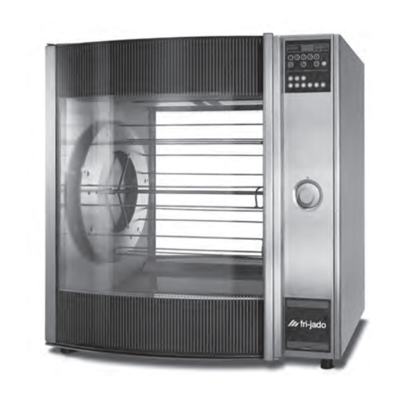
SERVICE MANUAL
STG ROTISSERIE OVEN MODELS
MODELS
Programmable controls STG8 I
Versions:
Solid Back
Pass-Through with rotor button
Model STG8 I
- NOTICE -
This manual is prepared for the use of trained Service Technicians and
should not be used by those not properly qualified. If you have attended
a trianing for this product, you may be qualified to perform all the proce-
dures in this manual.
This manual is not intended to be all encompassing. If you have not
attended a training for this product, you should read, in its entirety,
the repair procedure you wish to perform to determine if you have the
necessary tools, instruments and skills required to perform the procedure.
Procedures for which you do not have the necessary tools, instruments
and skills should be performed by a trained technician.
Reproduction or other use of this Manual, without the express written
consent of Fri-Jado, is prohibited.
Service Manual STG8 I form 9123548 rev. 05/2007
WWW.FRIJADO.COM
Advertisement
Table of Contents
Troubleshooting

Related Manuals for Fri-Jado STG


Summary of Contents for Fri-Jado STG
- Page 1 SERVICE MANUAL STG ROTISSERIE OVEN MODELS MODELS Programmable controls STG8 I Versions: Solid Back Pass-Through with rotor button Model STG8 I - NOTICE - This manual is prepared for the use of trained Service Technicians and should not be used by those not properly qualified. If you have attended a trianing for this product, you may be qualified to perform all the proce- dures in this manual.
- Page 2 Page 2 Service Manual STG8 I form 9123548 rev. 05/2007...
-
Page 3: Table Of Contents
TABLE OF CONTENTS INDEX Index ..........................3 General technical data ....................4 Technical data ..........................4 Programming instructions for the STG8 I ................. 5 Default parameters ........................9 Removal and replacement of parts for the STG8 I ............19 Right or left side panel .......................19 Top cover ..........................19 Glass operation panel with back plate ..................20 CPU board and display (Central Processor Unit) .................20... -
Page 4: General Technical Data
GENERAL TECHNICAL DATA GENERAL TECHNICAL DATA Thismanual covers the STG8 I series rotisserie ovens. Ovens will also be delivered in stacked versi- ons. • STG8 I - Oven with eight spits ( 32 to 40 chickens ) All of the information, illustrations and specifications contained in this manual are based on the latest product information available at the time of printing. -
Page 5: Programming Instructions For The Stg8 I
PROGRAMMING INSTRUCTIONS PROGRAMMING INSTRUCTIONS FOR THE STG8 I SETTINGS MENU ON - OFF ON - OFF °C - °F MANAGER MENU ----> IN MAIN MENU's Navigate by arrows up and down or the dial. Change value by left or right arrow. Entering Submenu (>) by "right"... - Page 6 PROGRAMMING INSTRUCTIONS MANAGER MENU NO - 1x - YES -50°C ..+50°C or -90°F ... +90°F NO - TIME 24HR - AM/PM DMY - MDY YES - NO -30°C ... +30°C or -54°F ... +54°F Page 6 Service Manual STG8 I form 9123548 rev. 05/2007...
- Page 7 PROGRAMMING INSTRUCTIONS SERVICE MENU access code 4878 MULTI - M BAKE - STGi 1 ..10 YES - NO YES - NO INPUT / OUTPUT TEST ----> Page 7 Service Manual STG8 I form 9123548 rev. 05/2007...
- Page 8 PROGRAMMING INSTRUCTIONS INPUT / OUTPUT TEST FRONTPANEL Allows a function test of all keys. MFMC INPUTS Shows the electronic board temperature and the dipswitch settings. MFMB INPUTS Shows the values of the actual inputs on the "Power and I/O" board. MFMB OUTPUTS Allows an output test on the outputs connected to the "Power...
-
Page 9: Default Parameters
1….60 Heater delta -30°C…+30°C or -4°F…+54°F Service ---> SERVICE MENU Device type STG-i Multi - M-bake - MultiM - Bake-i - STG-b - STG-i Correct factor 1….10 auto off (t6) 120 min. no….240 clean times --> Adding clnr (t1) Dry soak (t2) 0….30... - Page 10 PROGRAMMING INSTRUCTIONS DISPLAY AND KEYS Selection keys (3x) Display Start / Stop key Rotor rotation key OK / Enter key Turning knob On / Off key Cancel key SETTING THE STG8 I Press and hold the On/Off key during 2 seconds. The display lights up and the rotisserie is ON.
- Page 11 PROGRAMMING INSTRUCTIONS ADD A PROGRAM Press program key. Note: when a pin code has been set, first enter the pin code and confirm with OK. Go to add program with turning knob and con- firm with OK. Edit the program name with turning knob and confirm with 2x OK.
- Page 12 PROGRAMMING INSTRUCTIONS ADD A PROGRAM Select time table with turning knob and confirm with OK. Set the time of the grilling step and confirm with OK. Select temperature table with turning knob and confirm with OK. Set the temp. of the grilling step and confirm with OK.
- Page 13 PROGRAMMING INSTRUCTIONS PRE HEATING When pre heating step is activated in manager menu, the oven will start up with pre heat pro- gram after the program start. After reaching the pre heat temperature the display will indicate: load products. LOADING WITH PRODUCTS Press rotor key to start turning the rotor Press rotor key again to stop Load the rotisserie with products...
- Page 14 PROGRAMMING INSTRUCTIONS PROGRAM STOP Press cancel key. Select yes with turning knob and confirm with Page 14 Service Manual STG8 I form 9123548 rev. 05/2007...
- Page 15 PROGRAMMING INSTRUCTIONS OPTIONAL SETTINGS - Interrupting active program. - Editing a program. - Deleting of a program. - Running in test program. - Demo mode. INTERRUPTING ACTIVE PROGRAM Press start/stop key. Heating, blowers and rota- tion stops. Press start/stop key again to resume. EDIT A PROGRAM Press program key.
- Page 16 PROGRAMMING INSTRUCTIONS DELETE A PROGRAM Press program key. Note: when a pin code has been set, first enter the pin code and confirm with OK. Go to delete program with turning knob and confirm with OK. Now select the program to delete and confirm with OK.
- Page 17 PROGRAMMING INSTRUCTIONS DEMO MODE In the demo mode you can simulate a cooking cycle. This is used for exhibitions and runs just on 1 phase (L1). Go to the service menu and activate the access code 4878. Go to demo mode with the turning knoband adjust this on yes.
- Page 18 PROGRAMMING INSTRUCTIONS SWITCHING THE ROTISSERIE OFF Press and hold both keys On/Off and settings until the display light goes out and the rotisserie is OFF Page 18 Service Manual STG8 I form 9123548 rev. 05/2007...
-
Page 19: Removal And Replacement Of Parts For The Stg8 I
REMOVAL AND REPLACEMENT OF PARTS REMOVAL AND REPLACEMENT OF PARTS FOR THE STG8 I WARNING: Disconnect the electrical power to the machine at the main circuit box. Place a tag on the circuit box indicating the circuit is being serviced. RIGHT OR LEFT SIDE PANEL 1. -
Page 20: Glass Operation Panel With Back Plate
REMOVAL AND REPLACEMENT OF PARTS GLASS OPERATION PANEL WITH BACK PLATE 1. Remove the right side panel according prior procedure. 2. Remove the screws that secure the small top cover plate and remove the cover plate. 3. Remove the 2 nuts on the backside of the operating panel. -
Page 21: Keypad
REMOVAL AND REPLACEMENT OF PARTS KEYPAD 1. Remove the glass panel with back plate according prior procedure. 2. Remove the CPU board according prior procedure. 3. Remove the decal and degrease the surface of the glass. Gasket 4. Glue the new decal on its place. The corners on the steel back plate are the frame of reference for the decal. -
Page 22: Ceramic Element
REMOVAL AND REPLACEMENT OF PARTS CERAMIC ELEMENT 1. Remove the rotor discs, suction and fan plate according prior procedures. 2. Remove the 3 screws that secure the reflector ass. and lower the reflector. 3. Loosen the bolts that secure the cover plate and turn the cover plate open towards yourself. -
Page 23: Electronic Transformer
REMOVAL AND REPLACEMENT OF PARTS ELECTRONIC TRANSFORMER 1. Remove the right side panel according prior procedure. 2. Remove the screw that secures the cover plate and remove the cover plate. 3. Remove the wiring. 4. Remove the screw that secures the transfor- mer and remove the transformer. -
Page 24: High Limit Thermostat
REMOVAL AND REPLACEMENT OF PARTS HIGH LIMIT THERMOSTAT 1. Remove the right side panel according prior procedure. 2. Remove the suction and fan plate on the in- side of the oven. 3. Remove the thermostat-probe from the clip in the oven and guide it outside through the opening in the side wall. -
Page 25: Contactor
REMOVAL AND REPLACEMENT OF PARTS CONTACTOR 1. Remove the right side panel according prior procedure. 2. Disconnect the lead wires to the switch. 3. Push down on the locking tab and lift out and then up to remove it from the mounting brac- ket. -
Page 26: Blower Motor Bottom Rotisserie (Stacked Stg8 I)
REMOVAL AND REPLACEMENT OF PARTS BLOWER MOTOR BOTTOM ROTISSERIE (STACKED STG8 I) 1. Remove the right side panel according prior procedures. 2. Remove the rotor discs, suction and fan plate in the bottom oven. 3. Remove the wing nut on the fan blade and remove fan blade. -
Page 27: Heating Element
REMOVAL AND REPLACEMENT OF PARTS HEATING ELEMENT 1. Remove the rotor discs, right side panel, suction and fan plate according prior proce- dures. 2. Disconnect the wiring from the element. 3. Remove the mounting nut. 4. Remove the element from the mounting clip and pull it from the wall. -
Page 28: Door Adjustment (Left Side)
REMOVAL AND REPLACEMENT OF PARTS DOOR ADJUSTMENT (LEFT SIDE) 1. Remove the left side panel according prior procedure. 2. Loosen the nuts of the upper hinge. The door must be closed. 3. Loosen the locknut and adjust the bolt in or out to adjust the door. -
Page 29: Door Glass Outside
REMOVAL AND REPLACEMENT OF PARTS DOOR GLASS OUTSIDE 1. Lift the inner door out of the hinges and lay aside. 2. Remove the left side panel according prior procedure. 3. Remove the 2 nuts behind the top hinge. The door must be closed. 4. -
Page 30: Electrical Tests And Service Procedures
Place a tag on the circuit box indicating the circuit is being serviced. PROGRAMMING WITH FIPS In order to start communication between your computer and the STG intelligent, the following para- meters have to be checked and changed if necessary: Menu... - Page 31 ELECTRICAL TESTS AND SERVICE PROCEDURES THE PULL DOWN MENU’S The file menu. New: Opens a new file. The recipes field is made empty. And you will be asked if the current recipes have to be stored. Open: Opens an existing program. Save as: Saves the new made or modifide program.
- Page 32 ELECTRICAL TESTS AND SERVICE PROCEDURES The recipe menu New: To make a new recipe. Edit: Changing selected recipe. Sort: Sorting all recipes alphabetically. Delete: Deleting of selected recipe. The communication menu Select grill: Selection of IP address. Receiving all recipes from grill: Download all recipes.
- Page 33 ELECTRICAL TESTS AND SERVICE PROCEDURES The theme menu. Always adjust to Fri-Jado. The help menu About: Indication of the FIPS version. Page 33 Service Manual STG8 I form 9123548 rev. 05/2007...
- Page 34 ELECTRICAL TESTS AND SERVICE PROCEDURES The buttons New: Making of a new recipe. Edit: Changing selected recipe. Delete: Deleting of selected recipe. Sort: Sorting all recipes alphabetically. Send: Sending of a recipe to grill. Receive: Download of a recipe from grill. Existing recipe stays in grill. Connect: Making connection between computer and grill.
-
Page 35: Pt1000 Sensor Test
ELECTRICAL TESTS AND SERVICE PROCEDURES PT1000 SENSOR TEST 1. Remove the right side panel according prior Temperature Resistance procedure. °F °C ± 5 Ohms 1062 2. Remove the wiring from the sensor. 1082 3. Connect a temperature sensor to the probe for 1106 comparison. -
Page 36: Keypad Test
ELECTRICAL TESTS AND SERVICE PROCEDURES KEYPAD TEST To perform a keypad test the unit must be swit- ched off first. Another possibility is to activate this in the “service menu” under “I/O test” and “front panel”. There are 2 keypads. One for the selection keys in the top and one for the function keys below. -
Page 37: Part 1: General Troubleshooting List
TROUBLESHOOTING PART 1: GENERAL TROUBLESHOOTING LIST TROUBLESHOOTING THE STG8 I ROTISSERIE Symptom Possible causes No power to oven controls. 1. Main breaker open. 2. Fuse F1 burned. 3. Wiring loose. Main fuse or breaker blows. 1. Wiring incorrectly. 2. Heating element, drive motor, blower or magnetic switch shorted. -
Page 38: Part 2: Analytic Troubleshooting List
PART 2: ANALYTIC TROUBLESHOOTING LIST SERVICING AND REPAIRING OF THE STG8 I ROTISSERIE Servicing and repairing of the rotisseries STG 8 i This is an analytic description for servicing and repairing all major parts of the rotisseries and war- mers. It consists off 4 basic steps to recognize and solve the problems. These steps are: Symptoms. - Page 39 TROUBLESHOOTING Description of part Symptoms Possible causes Solving: checking/action PT-sensor Current temperature indi- No connection between Check the wiring. cation on display indicates wires. Check thin wire on sensor. 317°C - 603°F Current temperature indica- Full contact between wires of Check the wiring.
- Page 40 TROUBLESHOOTING Description of part Symptoms Possible causes Solving: checking/action Display operation panel and No illumination on display Wiring. Check the wiring. power I/O board Check the power on the po- wer I/O board by the green LED. Fuse burned. Check the 125 mA fuse on the power I/O board.
- Page 41 TROUBLESHOOTING Description of part Symptoms Possible causes Solving: checking/action Drive motor Motor doesn’t run Wiring. Check the wiring. Check the power to the motor. Coil malfunction Check resistance of the coils. Between whiteA and white wire 234Ω Between whiteA and brown wire 117Ω...
- Page 42 TROUBLESHOOTING Description of part Symptoms Possible causes Solving: checking/action Blower Blower doesn’t run Wiring. Check the wiring. Check the power on the blower. Coil malfunction. Check resistance of the coils. Between blue and brown wire 310Ω. Between blue and black wire 190Ω.
-
Page 43: Exploded Views & Partlists
EXPLODED VIEWS AND PARTLISTS EXPLODED VIEWS & PARTLISTS STG8 I Coated, Rotor button - Sheet Iron Work Page 43 Service Manual STG8 I form 9123548 rev. 05/2007... - Page 44 EXPLODED VIEWS AND PARTLISTS Item Qty. Partnumber Description 9170448 Frame, ass. 9170525 Heat shield 9170419 Side panel, left 9174005 Cover, removable 9170421 Side panel, top 9170531 Side panel, right 4288322 Screw M5 x 10, SS socket button head 9170425 Reinforcement, side plate, right 9170444 Support, gear motor 9170650...
- Page 45 EXPLODED VIEWS AND PARTLISTS STG8 I Coated, Rotor button - Components Page 45 Service Manual STG8 I form 9123548 rev. 05/2007...
- Page 46 EXPLODED VIEWS AND PARTLISTS Item Qty. Partnumber Description 9170426 Hinge, right 9170427 Hinge, left 9172273 Rotor shaft, ass., coated 9170536 Profile, magnet 9174631 Fastening, door handle 9173060 Electric panel, ass. 34-1 0166555 Earth symbol 34-2 9172330 Connecting block with bracket 34-3 9044564 Connecting block, 1,2,3...
- Page 47 Fuse housing 9172314 Flatcable, 14-pol. (i) 9070141 Magnet block 9070044 Connecting cable with plug 9172242 Meatfork STG 7, coated (8mm.) 4288321 Screw M5 x 16, SS socket button head 9171120 Fuse 5x20, ceramic T10A 9171018 Plug 9172252 Tensilock bolt M5x10, mushroom head, coated...
- Page 48 EXPLODED VIEWS AND PARTLISTS STG8+STG8 I Coated, Rotor button - Sheet Iron Work Page 48 Service Manual STG8 I form 9123548 rev. 05/2007...
- Page 49 EXPLODED VIEWS AND PARTLISTS Item Qty. Partnumber Description 9170448 Frame, ass. 9170525 Heat shield 9170419 Side panel, left 9174005 Cover, removable 9170421 Side panel, top 9170531 Side panel, right 4288322 Screw M5 x 10, SS socket button head 9170425 Reinforcement, side plate, right 9170444 Support, gear motor 9170650...
- Page 50 EXPLODED VIEWS AND PARTLISTS STG8+STG8 I Coated, Rotor button - Components Page 50 Service Manual STG8 I form 9123548 rev. 05/2007...
- Page 51 EXPLODED VIEWS AND PARTLISTS Item Qty. Partnumber Description 9170426 Hinge, right 9170427 Hinge, left 9172273 Rotor shaft, ass., coated 9170536 Profile, magnet 9174631 Fastening, door handle 9173060 Electric panel, ass. 34-1 0166555 Earth symbol 34-2 9172330 Connecting block with bracket 34-3 9044564 Connecting block, 1,2,3...
- Page 52 Magnet block 9172065 Castor without brake 9172066 Castor with brake 9070044 Connecting cable with plug 9172242 Meatfork STG 7, coated (8mm.) 4288321 Screw M5 x 16, SS socket button head 9171120 Fuse 5x20, ceramic T10A 9171018 Plug 9172252 Tensilock bolt M5x10, mushroom head, coated...
- Page 53 EXPLODED VIEWS AND PARTLISTS STG8+STG8 I SST, Solid Back - Sheet Iron Work Page 53 Service Manual STG8 I form 9123548 rev. 05/2007...
- Page 54 EXPLODED VIEWS AND PARTLISTS Item Qty. Partnumber Description 9170448 Frame, ass. 9170525 Heat shield 9170419 Side panel, left 9174005 Cover, removable 9170421 Side panel, top 9170531 Side panel, right 4288322 Screw M5 x 10, SS socket button head 9170425 Reinforcement, side plate, right 9170444 Support, gear motor 9170650...
- Page 55 EXPLODED VIEWS AND PARTLISTS STG8+STG8 I SST, Solid Back - Components Page 55 Service Manual STG8 I form 9123548 rev. 05/2007...
- Page 56 EXPLODED VIEWS AND PARTLISTS Item Qty. Partnumber Description 9170426 Hinge, right 9170427 Hinge, left 9170595 Rotor shaft, stainless steel 9170536 Profile, magnet 9174631 Fastening, door handle 9173060 Electric panel, ass. 34-1 0166555 Earth symbol 34-2 9172330 Connecting block with bracket 34-3 9044564 Connecting block, 1,2,3...
- Page 57 Fuse housing 9172314 Flatcable, 14-pol. (i) 9070141 Magnet block 9070044 Connecting cable with plug 9172153 Meatfork STG 7 (8mm.) 4288321 Screw M5 x 16, SS socket button head 9171120 Fuse 5x20, ceramic T10A 9171018 Plug 4288231 Tensilock bolt M5x10, stainless steel Page 57 Service Manual STG8 I form 9123548 rev.
-
Page 58: Electrical Diagrams
ELECTRICAL DIAGRAMS ELECTRICAL DIAGRAMS STG8 I Solid back - Circuit Diagram Page 58 Service Manual STG8 I form 9123548 rev. 05/2007... - Page 59 ELECTRICAL DIAGRAMS STG8 I Solid back - Wiring Diagram Page 59 Service Manual STG8 I form 9123548 rev. 05/2007...
- Page 60 ELECTRICAL DIAGRAMS STG8 I Rotor button - Circuit Diagram Page 60 Service Manual STG8 I form 9123548 rev. 05/2007...
- Page 61 ELECTRICAL DIAGRAMS STG8 I Rotor button - Wiring Diagram Page 61 Service Manual STG8 I form 9123548 rev. 05/2007...
- Page 62 ELECTRICAL DIAGRAMS STG8 I Rotorswitch(till 31-12-2006) - Circuit Diagram Page 62 Service Manual STG8 I form 9123548 rev. 05/2007...
- Page 63 ELECTRICAL DIAGRAMS STG8 I Rotorswitch (till 31-12-2006)- Wiring Diagram Page 63 Service Manual STG8 I form 9123548 rev. 05/2007...
- Page 64 Fri-Jado B.V. • P.O. Box 560 • 4870 AN • Etten-Leur • The Netherlands • tel +31 76 50 85 400 • fax +31 76 50 85 444 • info@frijado.com • www.frijado.com Service Manual STG8 I form 9123548 rev. 05/2007...
Need help?
Do you have a question about the STG and is the answer not in the manual?
Questions and answers